


26 Cisco 7000 and Cisco 7507 Chassis Replacement Instructions
Verifying the Installation
Troubleshooting the Installation
Follow the procedures in this section if the system does not restart and boot as expected. Most often,
problems you encounter while replacing the components in a new chassis are caused by power
supplies or processor modules that are not properly installed and therefore are not connected
properly inside the chassis. Use the following descriptions of the normal startup sequence to isolate
the problem, then use the troubleshooting procedures whenever the system fails to operate as
expected. If you are unable to successfully restart the system, contact a service representative.
LED Descriptions
Following are descriptions of the functions of the LEDs on the power supplies, chassis front panel,
and the RP. These are the states you should observe when you restart the system.
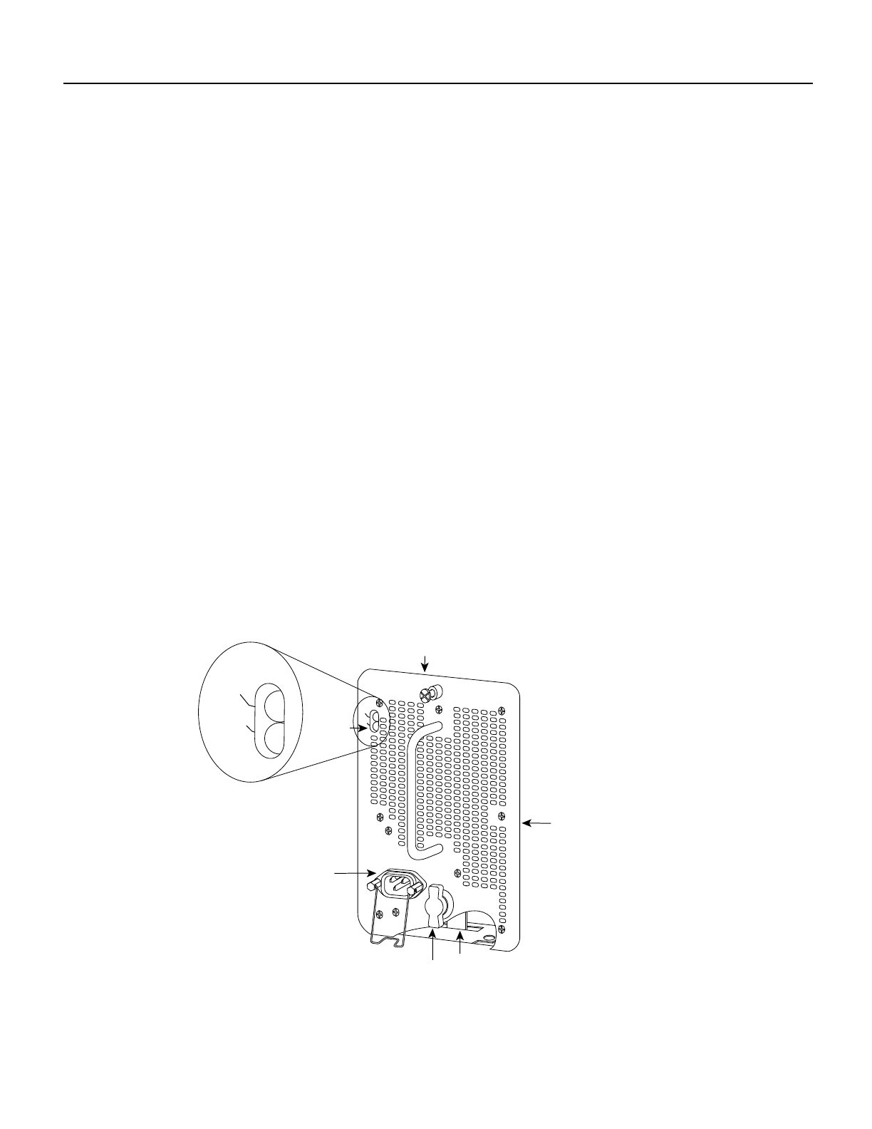
Power Supply LEDs
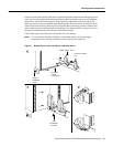
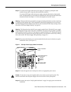
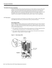
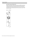
Each AC-input power supply contains AC power and DC fail LEDs and a power switch as shown in
Figure 12. The green AC power LED indicates that the power supply is turned on and is receiving
input AC power. The yellow DC fail LED is normally off, but goes on if the power supply shuts down
for any of the following reasons:
• Power supply DC section failure, which could be caused by loss of AC power (input line failure
or operator turned off system power), or an actual failure in the power supply
• Power supply shutdown initiated by the power supply because it detected an out-of-tolerance
temperature or voltage condition in the power supply
Figure 12 Power Supply LEDs
I
O
DC FAIL
AC POWER
Power supply
front panel
On/off switch
AC power
receptacle
LEDs
Captive
installation
screw
Locking device
H1314a
DC FAIL
AC POWER