


18 Cisco 7000 and Cisco 7507 Chassis Replacement Instructions
Moving System Components
Moving System Components
The following sections describe the procedures for removing each processor module and power
supply from the old chassis and installing it in the new chassis. Move and install all processor
modules before you move the power supplies. If you removed your existing chassis from an
equipment rack, the power supplies should already be removed; however, do not install them in the
replacement chassis until all processor modules are installed. Each interface processor slot in the
replacement chassis contains a blank board carrier. Remove the blank carriers individually as you
prepare to move each interface processor from the corresponding slot in the existing chassis.
If you are able to place both chassis close enough to avoid straining the connected interface cables
when you move the interface processors to the new chassis, you can leave the interface cables
connected. If you must disconnect the cables, label each cable with its slot and port number before
you disconnect it. You can also use the optional configuration worksheet provided at the end of this
document to record the cable positions. (For the Cisco 7000, refer to Figure 17, and for the Cisco
7507, refer to Figure 18.)
Caution Be sure to wear an ESD-prevention device while performing these steps. Review the
guidelines in the section “Preventing Electrostatic Discharge Damage” on page 10 if necessary.
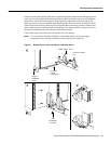
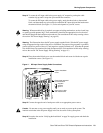
Step 1 Place the existing and replacement chassis side by side, if possible, and ensure that your
path between the two chassis is unobstructed.
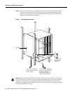
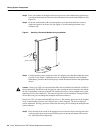
Step 2 Slip on a grounding strap or other ESD-prevention device and attach it to one of the captive
installation screws on a power supply in the rear of the chassis. (See Figure 1 or Figure 2.)
If you already removed the power supplies, clip the ESD-preventive strap to the captive
screw on any unfinished chassis surface.
Step 3 On the existing system, turn all power supply switches OFF (O) if you have not already
done so.
Step 4 On each interface cable connected to an interface processor, check the available slack to
determine whether removing the interface processor will strain the cable. Do not risk
straining the cables; if you are not sure if there is enough slack in the cable, disconnect it
before removing the interface processor.
Step 5 Check the slack on cables that are connected to the RP (in the Cisco 7000) or RSP2 (in the
Cisco 7507) console or auxiliary ports and also disconnect those cables if necessary.
Step 6 If you must disconnect the cables, label each one and use the configuration worksheet at
the end of this document to record the port connections ofeach cable to avoid crossing them
when you reconnect them to the new chassis. (For the Cisco 7000, refer to Figure 17, and
for the Cisco 7507, refer to Figure 18.) The section “Cable Strain Relief” on page 9
describes the different methods of strain relief used on the various interface types.
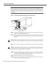
Moving the Processor Modules
Before removing any of the processor modules from the existing chassis, ensure that all system
power is off. Do not turn on the power for the replacement chassis until you have verified that all
components are installed properly.
After loosening the captive installation screws, use the ejector levers to remove and install processor
modules. The ejector levers help to ensure that backplane connectors on the card are fully seated in,
or fully ejected from, the backplane. (Refer to the ejector lever description on page 5.)