


Cisco 7000 and Cisco 7507 Chassis Replacement Instructions 17
Replacing a Rack-Mounted Chassis
Step 6 Position one person in the back of the rack to push the chassis out the front, and position
two people in front of the rack to support the chassis and lower it to the floor as it is pushed
forward out of the rack. Slowly push the chassis out of the front of the rack while the two
assistants in the front of the rack grasp the chassis along the metal undersides behind the
plastic front panels. When the chassis is clear of the rack, lower it to the floor.
Step 7 Position the removed chassis so that you will have room at the rear of the chassis to remove
the processor modules, and ensure that it will not be in the way when you install the
replacement chassis in the rack.
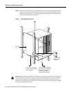
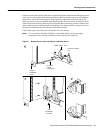
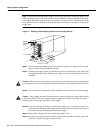
Step 8 Use a Number 2 Phillips screwdriver to remove the chassis ears from the removed chassis
and install them on the replacement chassis in the same position. Figure 7 shows the ears
mounted on the front of the chassis; if you are installing the system with the rear of the
chassis facing out of the front of the rack, use the mounting holes nearest the edge of the
ears (farthest from the bend) to mount them to the chassis.
Warning If you must lift the new chassis with the power supplies installed, ensure that you have
sufficient assistance to lift the chassis and support the rack. A fully configured chassis weighs
145 pounds, and the rear of the chassis is heaviest.
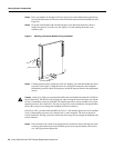
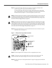
Step 9 With one person positioned on each side of the replacement chassis, grasp the underside of
the chassis behind the front plastic panels and lift the replacement chassis up until it is level
with the rails in the rack.
Step 10 Insert the rear of the chassis into the rack and lower it until the bottom of the chassis rests
on the rails.
Step 11 Slide the chassis back into the rack until the ears on the chassis are flush against the front
mounting strip on the rack.
Step 12 Use the four binder-head screws you removed in Step 5 to secure the ears to the front
mounting strip on the rack. (See Figure 7).
Step 13 Proceed to the section “Moving System Components” on page 18 to move the power
supplies and processor modules to the new chassis.
Caution When removing and replacing interface processors, be careful not to strain or bend
network interface cables.
Step 14 When all of the components are moved to the new chassis, reconnect all interface cables to
the interface ports. If you filled out the configuration worksheet, use it as a guideline. (For
the Cisco 7000, refer to Figure 17, and for the Cisco 7507, refer to Figure 18.)
Step 15 Proceed to the section “Verifying the Installation” on page 24 to verify that all components
are installed correctly.