


Cisco 7000 and Cisco 7507 Chassis Replacement Instructions 5
Product Overview
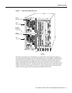
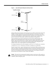
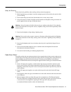
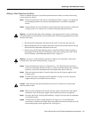
Figure 5 Cisco 7507 System Backplane Slot Key Guides
Spring-loaded ejector levers help to ensure that the processor modules are either fully inserted in the
backplane or fully dislodged from it. It is particularly important to use the ejector levers when
removing or installing processor modules because the bus connectors on the boards must be either
fully inserted in the backplane or fully dislodged from it when the system is operating. Any
processor module that is only partially connected to the backplane can hang the bus.
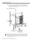
Captive installation screws at the top and bottom of each processor module faceplate, when
tightened, provide EMI shielding and also help ensure proper seating in the backplane. (See
Figure 8.) After using the ejector levers to install a processor module, tighten the top and bottom
captive installation screws to prevent the module from becoming partially dislodged from the
backplane. These screws must be tightened to meet EMI specifications.
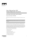
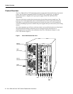
For complete descriptions of all system components, refer to the Cisco 7000 Hardware Installation
and Maintenance or Cisco 7507 Hardware Installation and Maintenance publications.
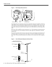
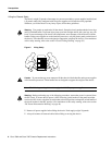
Figure 8 on page 19 shows a detail of the bottom ejector lever function. When you push the bottom
ejector lever upward, and push the corresponding top ejector lever downward, the ejector levers push
the board connectors into the backplane at the rear of the slot inside the chassis. Push the bottom
ejector lever a full 90 degrees upward, and push the upper ejector lever 90 degrees downward, to
ensure that the board connectors are fully seated in the backplane.
Caution The ejector levers ensure that the backplane connectors on the card are fully seated in, or
fully ejected from, the backplane. Failure to use the ejector levers could result in a partial backplane
connection, which can hang the system.
Interface processor
slots
H3126
RSP2
Key guides on interface
processors and RSP2
Bottom
Top
key guide
key guide
Rear of
processor card
Top
Bottom
Interface processor
slots
RSP2