


Cisco 7000 and Cisco 7507 Chassis Replacement Instructions 23
Moving System Components
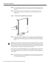
Step 13 To secure the AC-input cable in the power supply AC receptacle, push up the cable
retention clip up until it snaps into place around the connector.
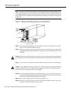
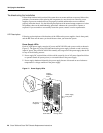
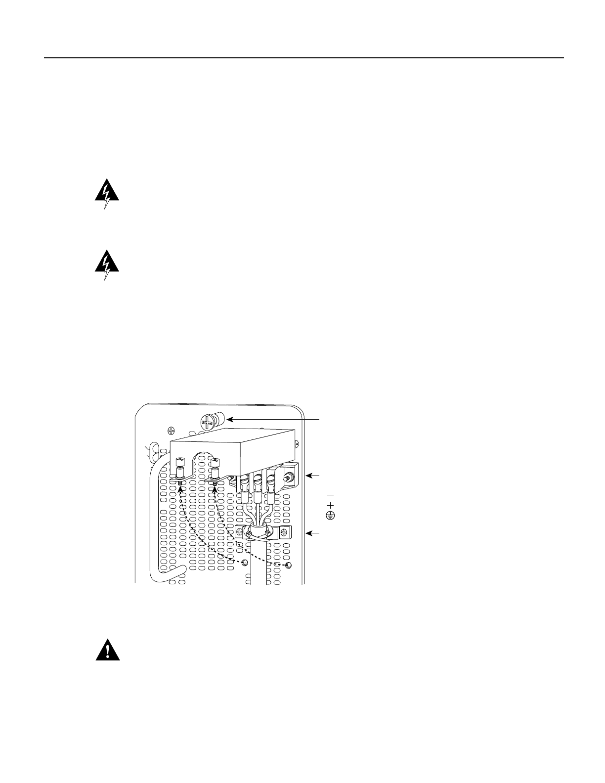
To secure the DC-input cable to the power supply, attach the three leads to the terminal
block, and then attach two nylon cable ties around the DC-input cable and the bracket near
the terminal block. (See Figure 11.) Color code depends on your DC source.
Warning When stranded wiring is required, use approved wiring terminations, such as closed-loop
or spade-type with upturned lugs. These terminations should be the appropriate size for the wires
and should clamp both the insulation and conductor. (For translations of this safety warning, refer to
the section “DC Power Supply Warning” on page 44.)
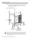
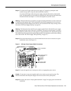
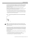
Warning The illustration shows the DC power supply terminal block. Wire the DC power supply
using the appropriate lugs at the wiring end, as illustrated. The proper wiring sequence is ground to
ground, positive to positive (line to L), and negative to negative (neutral to N). Note that the ground
wire should always be connected first and disconnected last. (For translations of this safety warning,
refer to the section “DC Power Supply Wiring Warning” on page 45.)
Step 14 Place the terminal block cover over the terminal block and secure it with the two captive
installation screws. (See Figure 11.)
Figure 11 DC-Input Power Supply Cable Connections
Step 15
Connect the opposite end of each power cable to an appropriate power source.
Caution Do not turn on any power supplies until you are ready to power up the system. The
interlock switch that locks the power supply in the slot also turns on the system power.
Step 16 Proceed to the section “Verifying the Installation” on page 24 to apply power and check the
installation.
OUT FAIL
INPUT POWER
DO NOT SHIP WITH POWER SUPPLY
INSTALLED
FASTENER TO BE FULLY ENGAGED
BEFORE OPERATING POWER SUPPLY
INPUT VOLTAGE : 40-72 V=
INPUT CURRENT : 24-13A
Captive installation
screw
Power leads attached
to terminal block
( ) negative
( ) positive
( ) ground
H2530
Nylon ties on cable
and metal bracket