


1-10
Cisco Connected Grid Ethernet Switch Module Interface Card Getting Started Guide
OL-23421-02
Chapter 1 Product Overview
Router Compact Flash Memory Cards
For more information on the Swap Drive feature, see:
http://www.cisco.com/en/US/docs/routers/connectedgrid/cgr2010/software/15_2_2_t/cgr2010_15_2_2
_t_swcg.html#wp2039791
The router supports a maximum of two compact flash memory cards. The router ships with one compact
flash card installed in Slot CF0 and supports a second, optional flash card that you can order with the
router or supply separately.
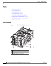
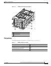
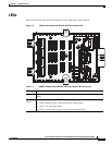
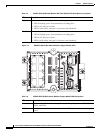
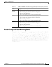
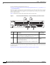
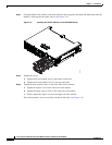
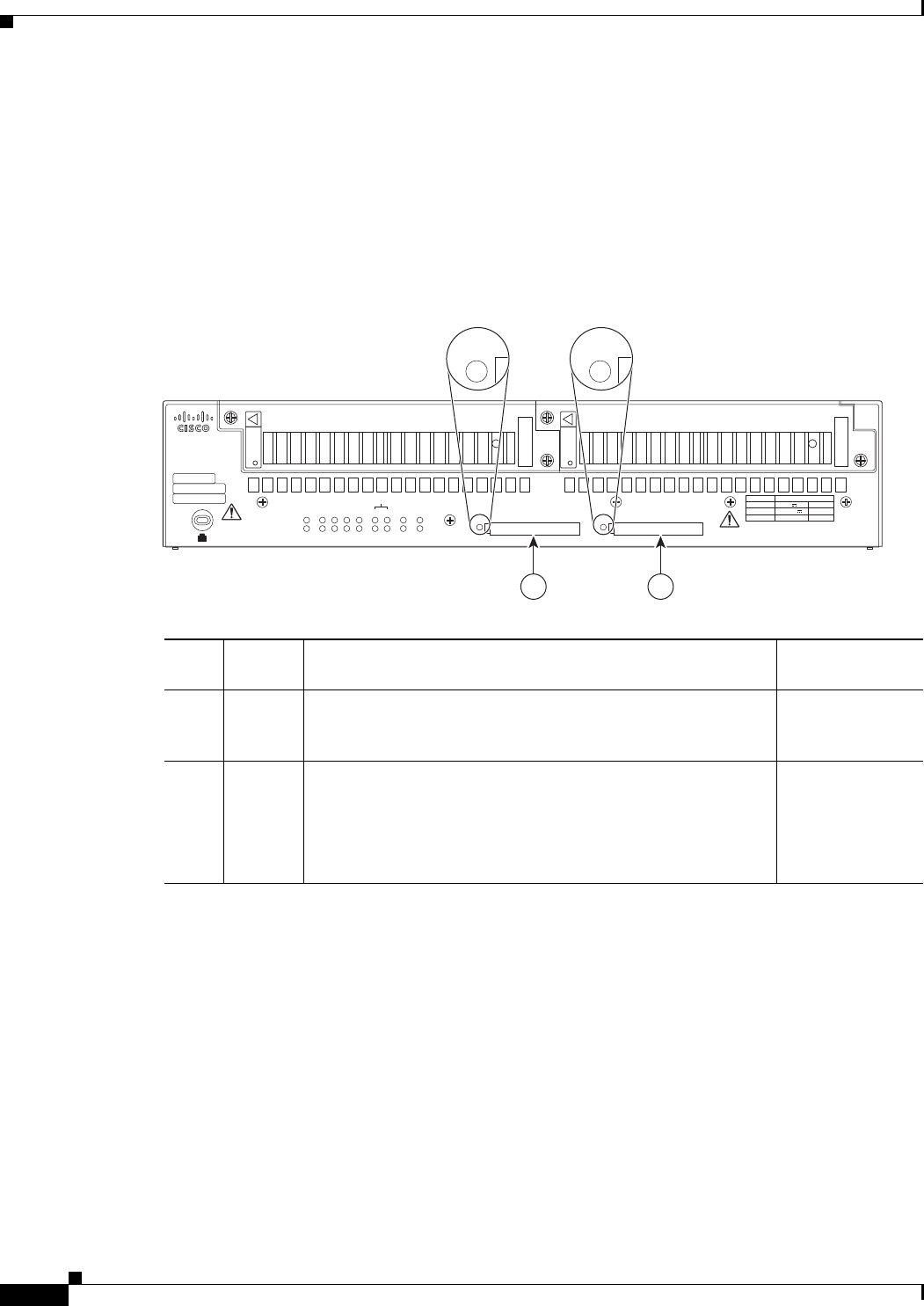
Figure 5 illustrates the location of the compact flash card slots on the router.
Figure 5 Cisco Connected Grid 2010 Router—Compact Flash Memory Card Slot Locations
For additional information about the router compact flash memory support, refer to the router hardware
installation guide at:
http://www.cisco.com/en/US/products/ps10977/prod_installation_guides_list.html
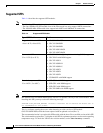
Item
Label on
Router Description
Cisco IOS
Interface Name
1 CF1 This slot supports an optional compact flash card that you can
order with the router or supply separately. The Connected Grid
Swap Drive feature is not supported on this slot.
flash1:
2 CF0 This is the required slot for use with the Connected Grid Swap
Drive feature. The router comes with a compact flash card
already installed in this slot.
The Connected Grid Swap Drive feature is supported on this
CF slot only.
flash or
flash0:
284213
PSU1 PSU2
PSU OK
PWR-150W-HV
PSU OK
PWR-150W-HV
SYS SPD SPD SPD SPD 2 0 1
USB
CON
ACT
SFP
0/1
EN
SFP
0/0
EN
GE
0/1
LINK
GE
0/0
LINK
PSU
231
CONSOLE
SLOT
CF1
DO NOT REMOVE DURING
NETWORK OPERATION
CF0
DO NOT REMOVE DURING
NETWORK OPERATION
Cisco Connected Grid Router 2000 Series
PS Type
LoV dc
HiV dc
V ac, 50/60 Hz
10A
2A
2A
Input Rating Per Sources
24-60V
100-270V
100-240V ~
CAUTION: This unit may have more than
one power source. Disconnect all power
sources before servicing to avoid
electric shock.
1 2
CF1 CF0