


A-2
Cisco Connected Grid Ethernet Switch Module Interface Card Getting Started Guide
OL-23421-02
Appendix A Cable and Connectors
Cables and Adapters
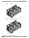
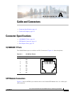
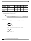
Figure A-2 Fiber-Optic SFP Module LC Connector
Warning
Invisible laser radiation may be emitted from disconnected fibers or connectors. Do not stare into
beams or view directly with optical instruments.
Statement 1051
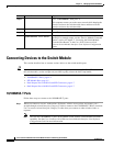
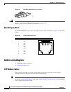
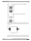
Dual-Purpose Ports
The 10/100/1000BASE-T ports on the dual-purpose ports use RJ-45 connectors. Figure A-3 shows the
pinouts.
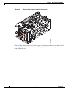
Figure A-3 10/100/1000 Port Pinouts
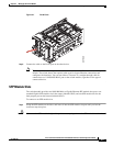
Cables and Adapters
• SFP Module Cables, page A-2
• Cable Pinouts, page A-4
SFP Module Cables
Each port must match the wave-length specifications on each end of the cable, and for reliable
communications, the cable must not exceed the allowable length.
Note The maximum operating temperature of the switch varies depending on the type of SFP module that you
use. See the “Supported SFP Models” table in the “Supported SFPs” section on page 1-6 for information
on the supported temperature ranges.
58476
60915
231 45678Pin Label
1
2
3
4
5
6
7
8
TP0+
TP0-
TP1+
TP2+
TP2-
TP1-
TP3+
TP3-