


4-7
Cisco Connected Grid Ethernet Switch Module Interface Card Getting Started Guide
OL-23421-02
Chapter 4 Managing the Switch Module
Connecting Devices to the Switch Module
For detailed instructions on installing, removing, and connecting to SFP modules, see the SFP module
documentation.
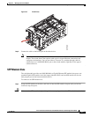
Dual-Purpose Port with RJ-45 and SFP Connectors
The Gigabit Ethernet port GE0/1 on the switch module consists of a pair of one RJ-45 connector
(topmost port) and one SFP module connector (bottom port).
This dual-purpose port is considered as a single interface. The two connectors are not redundant
interfaces—the switch module activates only one connector of the pair at a time.
If the dual-purpose port is configured as media-type RJ-45, the speed of the connection can be manually
set to either 10, 100 or 1000 Mb/s (10/100/1000BASE-T specifications). The default speed setting is
always enabled to AUTONEGOTIATION. It will automatically negotiate to whatever speed is set on the
other end of the connection.
If the dual-purpose port is configured as media-type SFP, the speed is dependent on the module type you
are using, either a 100FX or a 1000BASE-X SFP module. The port will automatically detect the module,
and the speed is set based on the media type. The other end of the connection will have to be of the same
media type in order to establish the link.
Note Even when operating at 100 Mb/s, the dual-purpose ports (and the SFP-only module slots) use the frame
size that is set with the system mtu jumbo global configuration command.
By default, the dual-purpose ports and the SFP-only module slots are network node interfaces (NNIs).
By default, the switch module dynamically selects the dual-purpose port media type that first links up.
However, you can use the media-type interface configuration command to manually select the RJ-45
connector or the SFP module slot.
Note In auto-select mode, if both copper and fiber-optic signals are simultaneously detected, the switch
module gives preference to SFP mode.
For configuration information, see “Configuring a Dual-Purpose Port” in Chapter 8, “Configuring
Interfaces,” in the Cisco 2010 Connected Grid Ethernet Switch Module Interface Card Software
Configuration Guide.
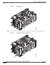
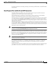
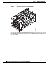
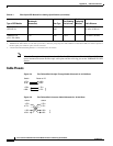
The following illustration shows an Ethernet cable connected to the RJ-45 connector of the dual-purpose
port (GE0/1). It also shows an SFP cable connected to the standard SFP module slot (GE0/2).