


CHAPTER
2-1
Cisco Connected Grid Ethernet Switch Module Interface Card Getting Started Guide
OL-23421-02
2
Installation
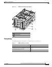
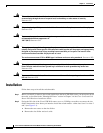
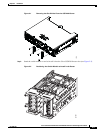
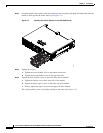
This section describes how to install the switch module in Cisco CGR 2010 routers. The switch module
occupies two of four slots on the I/O side of the router. This chapter includes the following topics:
• Pre-Installation
• Installation
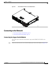
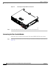
• Connecting to the Network
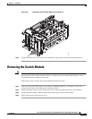
• Removing the Switch Module
Pre-Installation
Before installing the switch module, verify these guidelines are met:
• Clearance to the I/O-side view is such that the LEDs can be easily read
• Cabling is away from sources of electrical noise, such as radios, power lines, and fluorescent
lighting fixtures. Make sure that the cabling is away from other devices that might damage the
cables.
• Airflow around the switch module and through the vents is unrestricted
• Temperature around the unit does not exceed 140°F (60°C). If the switch module is installed in a
closed or multirack assembly, the temperature around it might be higher than normal room
temperature.
• Relative humidity around the switch module does not exceed 95 percent (noncondensing)
• Altitude at the installation site is not higher than 10,000 feet
• For 10/100 and 10/100/1000 fixed ports, cable lengths from the switch module to connected devices
are not longer than 328 feet (100 meters)
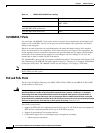
Installation Warning Statements
This section includes the basic installation warning statements. Translations of these warning statements
appear in the Regulatory Compliance and Safety Information for the Cisco CGS 2520 Switches and the
Regulatory Compliance and Safety Information for Cisco Connected Grid Router 2000 Series Routers
documents.