


3-8
Cisco UCS C22 Server Installation and Service Guide
OL-26646-01
Chapter 3 Maintaining the Server
Preparing for Server Component Installation
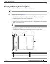
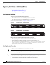
Removing and Replacing the Front Chassis Panel
To remove or replace the front chassis panel of the server, follow these steps:
Tip Remove this panel only if you are instructed to do so in a procedure in this book.
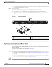
Step 1 Remove the front chassis panel (see Figure 3-3):
a. Remove the top cover from the server as described in Removing and Replacing the Server Top
Cover, page 3-7.
Note If you have a newer version of the server, the front chassis panel has no screws but instead lifts off after
the top cover is removed. If you have an older version of the server that has screws on the front chassis
panel, continue with the following steps.
b. Use a #2 Phillips-head screwdriver to remove the two screws that secure the front chassis panel to
the chassis (see Figure 3-3).
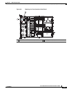
c. Push the panel toward the server rear about one-half inch (1.27 cm), until its front flanges are free
from the front panel lip.
d. Lift the panel straight up from the server and set it aside.
Step 2 Replace the front chassis panel:
a. Set the front chassis panel back in place, about one-half inch (1.27 cm) behind the front panel lip.
Note The flanges on the panel must slide under the front chassis lip.
b. Slide the front chassis panel toward the front chassis lip, sliding the flanges on the panel underneath
the front chassis lip.
Note If you have a newer version of the server, the front chassis panel has no screws but is instead held in
place by spring-clips. If you have an older version of the server that has screws on the front chassis panel,
continue with the following steps.
c. Replace the two screws that secure the panel to the chassis (see Figure 3-3).
d. Replace the top cover to the server as described in Removing and Replacing the Server Top Cover,
page 3-7.