


3-33
Cisco UCS C22 Server Installation and Service Guide
OL-26646-01
Chapter 3 Maintaining the Server
Installing or Replacing Server Components
c. Remove the top cover as described in “Removing and Replacing the Server Top Cover” section on
page 3-7.
d. Lift straight up on both ends of the PCIe riser to disengage its circuit board from the socket on the
motherboard.
e. If the riser has a card installed, remove the card from the riser.
Step 2 Install a new PCIe riser:
a. If you removed a card from the old PCIe riser, install the card to the new riser (see Replacing a PCIe
Card, page 3-34).
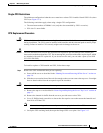
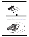
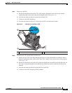
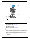
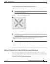
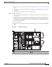
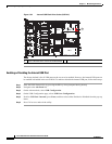
b. Position the PCIe riser over its socket on the motherboard and over the chassis alignment features
(see Figure 3-20). The metal shell of the riser has alignment tabs that fit into slots in the chassis.
c. Carefully push down on both ends of the PCIe riser to fully engage its circuit board connector with
the socket on the motherboard.
d. Replace the top cover.
e. Replace the server in the rack, replace cables, and then power on the server by pressing the Power
button.
Figure 3-20 Replacing the PCIe Riser
1 Chassis alignment points for PCIe riser 1 2 Chassis alignment points for PCIe riser 2
PCIe 1
PCIe 2
PSU 1
SYS FAN1
SYS FAN2
SYS FAN3
SYS FAN4
CPU 1
CPU 2
SYS FAN5
285210
1
2
1