


3-25
Cisco UCS C22 Server Installation and Service Guide
OL-26646-01
Chapter 3 Maintaining the Server
Installing or Replacing Server Components
Single-CPU Restrictions
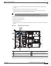
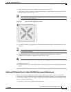
The minimum configuration is that the server must have at least CPU1 installed. Install CPU1 first, then
CPU2 (see Figure 3-12).
The following restrictions apply when using a single-CPU configuration:
• The maximum number of DIMMs is six (only the slots controlled by CPU1 are active).
• PCIe slot 2 is unavailable.
CPU Replacement Procedure
Caution CPUs and their motherboard sockets are fragile and must be handled with care to avoid damaging pins
during installation. The CPUs must be installed with heatsinks and their thermal pads to ensure proper
cooling. Failure to install a CPU correctly might result in damage to the server.
Caution The Pick-and-Place tools used in this procedure are required to prevent damage to the contact pins
between the motherboard and the CPU. Do not attempt this procedure without the required tools, which
are included with each CPU option kit. If you do not have the tool, you can order a spare (Cisco PID
UCS-CPU-EN-PNP).
To install or replace a CPU heatsink and CPU, follow these steps:
Step 1 Remove the CPU and heatsink that you are replacing:
a. Power off the server as described in the “Shutting Down and Powering Off the Server” section on
page 3-6.
b. Slide the server out the front of the rack far enough so that you can remove the top cover. You might
have to detach cables from the rear panel to provide clearance.
Caution If you cannot safely view and access the component, remove the server from the rack.
c. Remove the top cover as described in “Removing and Replacing the Server Top Cover” section on
page 3-7.
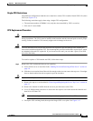
d. Remove the internal air baffle from the server to provide access to the CPUs.
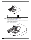
e. Use a #2 Phillips-head screwdriver to loosen the four captive screws that secure the heatsink and
then lift it off of the CPU.
Note Alternate loosening each screw evenly to avoid damaging the heatsink or CPU.
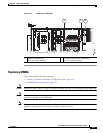
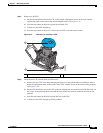
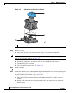
f. Unclip the CPU retaining latch, then open the hinged CPU cover plate. See Figure 3-13.