


3-17
Cisco UCS C22 Server Installation and Service Guide
OL-26646-01
Chapter 3 Maintaining the Server
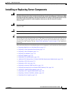
Installing or Replacing Server Components
c. Thread the two front operation panel ribbon cables back through the opening in the backplane
assembly.
d. Reconnect the two ribbon cables to the front operations panel board.
Open a hinged ribbon-cable connector and insert the end of a ribbon cable squarely into the
connector until it stops, and then close the hinged connector.
Note The side of the ribbon cable end that is colored blue should face upward.
e. Reconnect all cables to the backplane, including all RAID controller cables and all power cables.
f. Replace all drives to the server.
g. Replace the front chassis panel.
h. Replace the top cover.
i. Replace the server in the rack, replace cables, and then power on the server by pressing the Power
button.
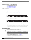
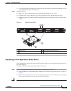
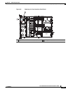
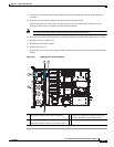
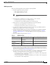
Figure 3-9 Replacing the Drive Backplane
1 Front panel control board cable connectors 3 Location of opening in backplane assembly
for front operations panel ribbon cables
2 Backplane securing screw locations (two on
backplane assembly and two on exterior sides)
–
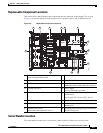
PCIe 1
PCIe 2
SYS FAN1
SYS FAN2
SYS FAN3
SYS FAN4
CPU 1
CPU 2
SYS FAN5
285207
PSU 1
1
2
2 3
2