


3-9
Cisco UCS C22 Server Installation and Service Guide
OL-26646-01
Chapter 3 Maintaining the Server
Preparing for Server Component Installation
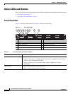
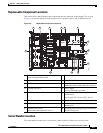
Replaceable Component Locations
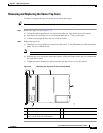
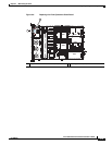
This section shows the locations of the components that are discussed in this chapter. The view in
Figure 3-4 is from the top down with the top cover, front chassis panel, and air baffle removed.
Figure 3-4 Replaceable Component Locations
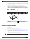
Serial Number Location
The serial number for the server is printed on a label on the top of the server, near the front.
1 Drives (hot-swappable,
accessed through front panel)
9 RTC battery on motherboard
2 Front operations panel board 10 PCIe riser 2 (PCIe slot 2)
3 Drive backplane 11 Trusted platform module socket on
motherboard (not visible under PCIe riser 2)
4 Cooling fans (five) 12 Power supply
(accessed through rear panel)
5 DIMM slots on motherboard (twelve) 13 Integrated SAS RAID connectors on
motherboard
(left to right, SCU_Port 0, SCU_Port 1)
6 CPUs and heatsinks (two) 14 SW RAID 5 key header on motherboard
7 PCIe riser 1 (PCIe slot 1) 15 RAID SCU option ROM header on
motherboard
8 Internal USB 2.0 port
(on motherboard under PCIe riser 1)
16 Mounting point for SuperCap power module
(RAID backup unit)
PCIe 1
PCIe 2
SYS FAN1
SYS FAN2
SYS FAN3
SYS FAN4
CPU 1
CPU 2
SYS FAN5
285200
PSU 1
1
2 3 5 74 6
8
12
10
9
11
13
14
15
16