


27
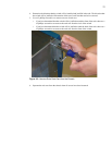
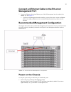
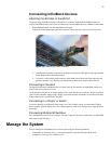
Connect an Ethernet Cable to the Ethernet
Management Port
3. Connect an Ethernet cable to the Ethernet port of the left Management Interface module (slot
number 15). See Figure 2-7.
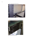
a. If you have two Management Interface modules, you may also want to connect an Ethernet
cable to the standby module (slot 16) to maintain Ethernet connectivity in the event of a
fail-over.
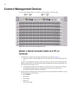
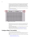
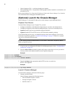
Recommended Management Configuration
The diagram below shows the recommended management port connections. To have constant access to
the chassis remotely, redundantly connect the serial ports on two Management Interface cards to a
terminal server.
Figure 2-7: Recommended Management Configuration
Power on the Chassis
Use only the power cable provided with your InfiniBand system.
4. Remove the power cords from the shipping package.
One power cord UL rated 12 Amps/125 VAC or greater is provided by default. If you have a
high-availability unit, you will have a second power cord.