


50
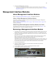
7. If the Master Management Interface module was removed, the standby module becomes active.
The “Master” led becomes green.
8. Install a blanking panel in the empty bay, or refer to “Installing a Management Interface Module”
on page 50 to replace the Management Interface module.
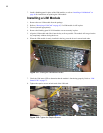
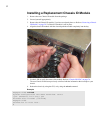
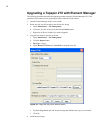
Installing a Management Interface Module
1. Remove the new Management Interface module from the package.
2. Ground yourself appropriately.
3. Refer to “Removing a Management Interface Module” on page 49 if a Management Interface
module is still in place.
4. Remove the blanking panel if a Management Interface module was not previously in place.
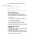
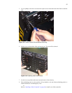
5. Align the Management Interface module and push the module completely into the bay.
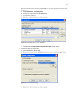
6. Use the LEDs to verify the status of the management interface module and the corresponding core
card. Refer to “Management Interface Module LEDs” on page 71.
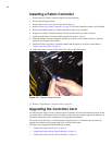
7. Connect the Ethernet or serial cables to the ports.
8. Tighten the outside screws with a #1 phillips screwdriver.
Chassis ID Modules
About Chassis ID Modules
Refer to “Chassis ID Module” on page 19 for additional information.
Failed Chassis ID Module
If you believe a chassis ID module has failed, contact technical support.
Refer to “Chassis ID LEDs” on page 74 and “Monitor the Cards” on page 79 for monitoring
information.
• A failure of the Chassis ID module will cause the yellow error LEDs to be lit on the Chassis ID
module. The System Status LED will turn yellow as well.
CAUTION: Never remove a Chassis ID unless Technical Support has specifically instructed you to do
so.
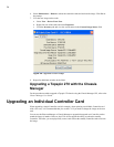
Locating the Chassis ID Module
The Chassis ID module is located on the back of the chassis. Refer to Figure 1-2 for a diagram of the
chassis.
Removing a Chassis ID Module
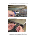
1. If you must remove a Chassis ID module, verify that you have a means of covering the slot before
removing the module. Do not remove the module unless you have a replacement or a blanking
panel for the slot, as overheating may occur.
2. Ground yourself appropriately.