


69
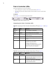
Fan LEDs
Location
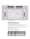
The Fan LEDs are located at the top of each Fan tray module. Refer to “Front Panel LEDs” on page 66.
In addition, replicas of the Fan Tray LEDs are positioned on the back of the chassis. Refer to
“Management Interface Module LEDs” on page 71.
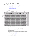
Interpreting the Fan LEDs
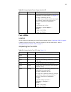
Table 5-3: Interpreting the Power Supply Identify LED
Color State Indication
Yellow blinking Identify. Assists in identifying a particular Field
Replaceable Unit on the chassis. (see Figure 5-3)
This state is initiated by the user.
This LED status is initiated manually by using the
diag LED test. Refer to the Command Line
Reference Guide for more information.
Example:
To run identity test on fan 1:
config mode -> power-supply 1 ->
test led ->
-> start - start flashing
-> stop - stop flashing
Table 5-4: Interpreting the Fan LEDs (see Figure 5-1)
Color State Indication
Green and
Yellow
off No power to the fan tray, or LED failure.
Green solid on Fan tray running with no detected errors.
Green off No power to the fan tray, LED failure, or yellow
LED is ON.
Yellow off Fan tray running with no errors detected.
Yellow solid on Operator intervention required. Failure detected
within the fan tray.
Yellow blinking Identify. Assists in identifying a particular Field
Replaceable Unit on the chassis.
This state is initiated by the user.
This LED can be initiated manually by using the
diag LED test. Refer to the Command Line
Reference Guide for more information.
Example:
To run the identity test on fan 1:
config mode -> diag fan 1 ->
test led ->
-> start - start flashing
-> stop - stop flashing