


38
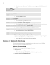
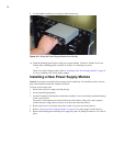
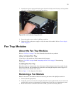
9. Use the handle to pull the power supply module from the bay.
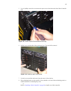
Figure 3-3: Pulling the Power Supply Module from the Bay
10. Install the blanking panel in place of the power supply module. The device should never be run
without either a blanking panel or module in any bay, as overheating may occur.
or
Install a new Power Supply module. Refer to “Installing a New Power Supply Module” on page 38
if you are installing a new Power Supply module.
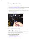
Installing a New Power Supply Module
Caution: Never place your hand inside an empty card or module bay. You should never have cause to
place a hand anywhere inside the Topspin 270 chassis.
To insert a power supply unit:
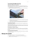
1. Remove the new power supply from the package.
2. Ground yourself appropriately.
3. Insert the Topspin-provided power cord into the receptacle, if one is not already connected and plug
it into a power-source.
The power cord receptacles are located on the back of the chassis. Each power cord receptacle
controls the power supply that is closest to it (on the same end of the chassis).
4. Remove the bezel cover from the front of the switch, if you have not already done so.
5. Refer to “Removing a Power Supply Module” on page 36, if a power supply is still in the bay.
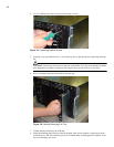
6. Remove the blanking panel from the power supply bay with a #1 phillips screwdriver, if it is still in
place.