


Professional Video Distribution Switch Crestron CNX-PVID8x3
6 • Professional Video Distribution Switch: CNX-PVID8x3 Operations Guide - DOC. 8159A
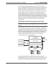
connect independent video sources to the CNX-PVID8x3. Each connector is
supplied with RCA terminators (75 ohm). The terminators should remain attached
unless the INPUT connectors of multiple units are connected (loop-through). Refer
to "Signal Distribution to More than Eight Rooms" on page 21 for a description and
illustration about loop-through. The last unit in the loop must have terminators
installed.
All video inputs have a video sensor so that the power status of all components can
be reported. Only inputs with sync can be reliably detected (composite or
luminance).
OUTPUT (RCA Connectors)
There are three levels of eight RCA jacks (24 total) for single ended (local mode)
video.
NOTE: The information on the OUTPUT RCA connectors and OUTPUT RJ-45
connectors are identical; they are not independently controllable.
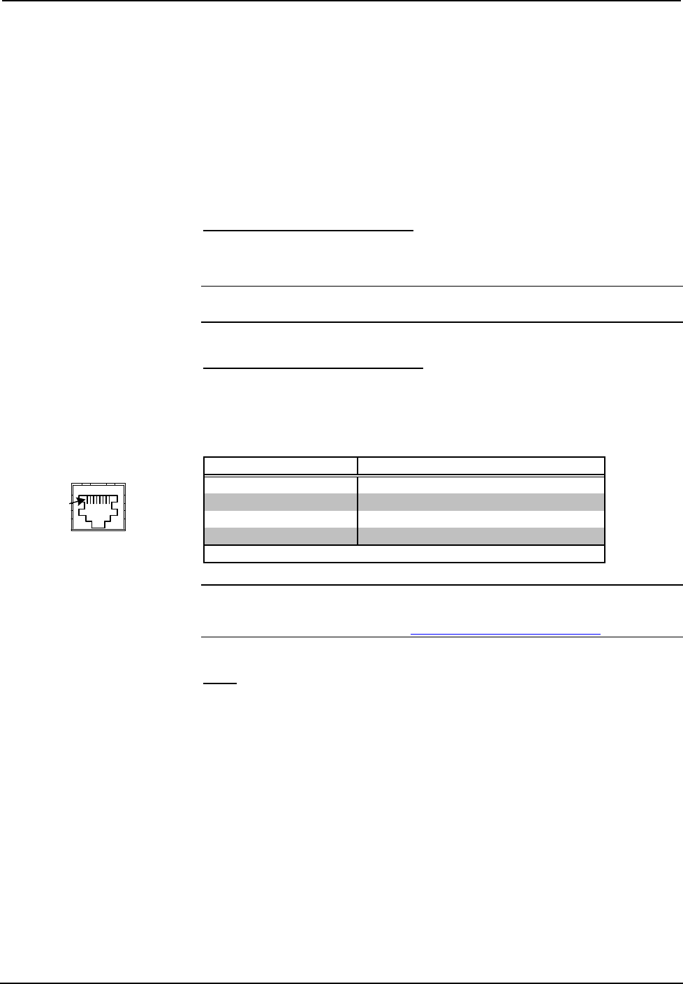
OUTPUT (RJ-45 Connectors)
There are eight RJ-45 connectors for differential video (CAT5 mode). The outputs
are grouped into three pairs and correspond to the INPUT levels as shown in the
table after this paragraph. Use a standard CAT5 cable.
Pairing of RJ-45 OUTPUT Connector Pins with respect to the INPUT Levels
PAIRED PIN # ASSOCIATED INPUT LEVEL
1* and 2 1
3 and 6 2
4 and 5 3
7 and 8 not connected
* While facing the rear panel of the unit, pin 1 is located at the left side of the port.
NOTE: For additional information on video connections over CAT5, refer to the
latest version of the Crestron CAT5 Wiring Reference Guide (Doc. 6137) which is
available from the Crestron website (http://www.crestron.com/manuals
).
NET
This 4-pin terminal block connector is used to connect the CNX-PVID8x3 to the
Cresnet system. Refer to "Network Wiring" on page 8 for details.
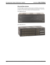
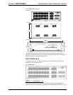
CNX-PVID8x3 Indicators
There are 29 LED indicators located on the front panel of the CNX-PVID8x3, and
one on the back panel. Refer to the following illustration and descriptions.
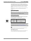
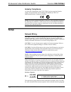
JACK, REAR VIEW
(TAB POSITION DOWN)
Pin 1
RJ-45 Pinout