Crestron CNX-PVID8x3 Professional Video Distribution Switch
Operations Guide - DOC. 8159A Professional Video Distribution Switch: CNX-PVID8x3 • 21
Configuration Wiring Guidelines
Once a configuration is chosen and any appropriate physical modifications to the
CNX-PVID8x3 have been made, wiring can begin. Refer to the following guidelines.
• Begin adding component sources at input 16 and work toward input 1 on all
three levels.
• Add composite sources beginning at input 1. In the out-of-box
configuration, add sources on level 1. For any other configuration, begin on
level 3.
• S-video is places on levels 1 and 2 on any unused inputs.
• Wire S-video Y on level 1; C on level 2. Wire component with green on
level 1 (Y), blue on level 2 (Pb), and red on level 3 (Pr). This keeps sync for
all sources on level 1, which greatly simplifies troubleshooting.
• Remember to leave terminators in place on any unused input on any level.
RCA outputs can be wired using the same guidelines as inputs: component beginning
as output 8 and composite beginning at output 1. When using the CAT5 outputs,
remember that each CAT5 connector represents all three levels of the unit.
Signal Distribution to More than Eight Rooms
Each CNX-PVID8x3 is capable of distributing video to eight rooms, maximum. It is
possible to expand distribution to more rooms, if additional CNX-PVID8x3s are
introduced to the system. Crestron recommends a maximum of four CNX-PVID8x3s
per system. Therefore, video can be distributed to a maximum of 32 rooms. Each
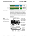
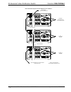
input to the unit has two RCA jacks connected in parallel (per level). Use one of the
jacks for loop-through, as shown in the illustration after this paragraph.
NOTE: The last unit in the loop-through connection must have terminators
installed.


