


Crestron CNX-PVID8x3 Professional Video Distribution Switch
Operations Guide - DOC. 8159A Professional Video Distribution Switch: CNX-PVID8x3 • 19
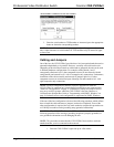
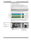
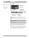
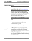
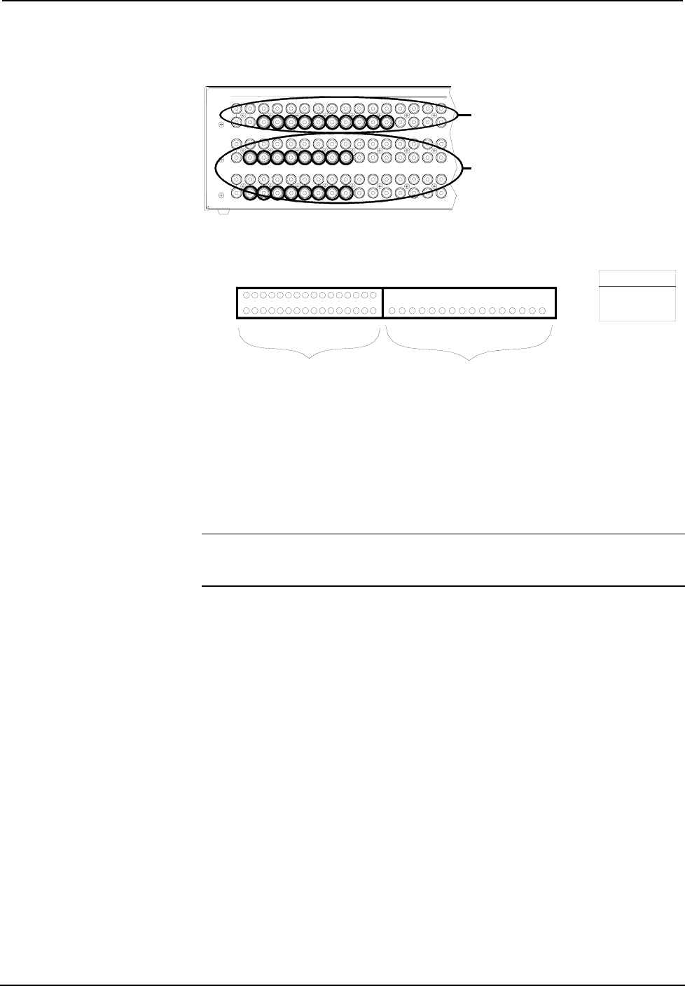
Illustration of Composite/S-Video Only Configuration
Cabling and Jumpering Internal
Boards:
Cable between level 1 and level 3
is in place.
Nine jumpers remain in their
original location (no jumpers
on the jumper holder).
13
17 18 19 20 21 22 23 24 25 26 27 28 29
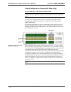
16 (OR MORE) COMPOSITE SOURCES*
ARE PERMITTED.
NOTE: THE LABELING OF INPUTS 17
THROUGH 32 BECOMES USEFUL
WHEN PROGRAMMING.
1
UP TO 16 S-VIDEO SOURCES ARE PERMITTED
NOTE: WHEN THERE ARE FEWER THAN
16 S-VIDEO SOURCES, COMPOSITE
SOURCES CAN CONNECT TO LEVEL 1.
I
1 2 3 4 5 6 7 8 9 10 11 12 13 14 15 16
REFER TO THE LOGICAL DEPICTION
(SHOWN BELOW) OF THE PHYSICAL
CONNECTIONS (SHOWN ABOVE).
LOGICAL DEPICTION:
LEVEL 2
LEVEL 1
INPUTS
CE
STRONCRE
LE KLEROCINC.TRONICS NHG , 7607 4J.. SAU
PHYSICAL CONNECTIONS:
5
3
2
1 234
106789
INPUT
11 12
SWITCHABLE TO:
OUTPUT LEVEL 1
OUTPUT LEVEL 2
*COMPOSITE SOURCES CAN CONNECT
TO LEVEL 1 (WHEN THERE ARE
FEWER THAN 16 S-VIDEO SOURCES).
HOWEVER, THE TOTAL NUMBER
OF COMPOSITE AND S-VIDEO
SOURCES CANNOT EXCEED 32.
30 31 32
LEVEL 3
COMPOSITE SOURCES*:
PHYSICALLY CONNECT TO LEVEL 3
(INPUTS 1 THROUGH 16),
BUT ARE LOGICALLY AN
EXTENSION OF LEVEL 1.
S-VIDEO SOURCES:
PHYSICALLY CONNECT TO LEVELS 1 & 2
(INPUTS 1 THROUGH 16) ONLY.
14 15 16
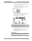
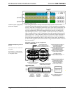
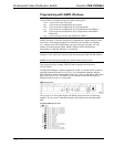
Split Board Configuration (Limited Quantity of Any Input
Type)
AKA: 8 Video, Up to 8 S-Video/Video, and Up to 8 Component/S-Video/Video
Sources
NOTE: Dealing with a system that contains more than 16 sources? This
configuration may be preferred as long as the system does not contain more than
eight component video sources.
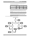
This configuration somewhat mimics the out-of-the-box configuration, but there are
differences. The first difference is that jumpers need to be removed and the cable
assembly must be attached. Refer to "Cabling and Jumpers" on page 12 for details.
Secondly, even though the total number of mixed sources allowed in this
configuration is greater, it does not permit more than eight component sources at any
time.
The following figure illustrates the effect of connecting the cable between the level 1
and level 3 boards and removing the jumpers from the level 3 board. Eight level 3
inputs become an extension of the level 1 board, resulting in a logical 24X8 switcher
on level 1, a 16X8 switcher on level 2; and an 8X8 switcher on level 3.