


Crestron CNX-PVID8x3 Professional Video Distribution Switch
Operations Guide - DOC. 8159A Professional Video Distribution Switch: CNX-PVID8x3 • 15
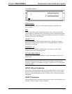
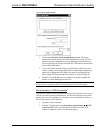
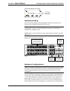
Feet Location (Bottom View of Unit)
ATTACH FEET
NEAR CORNERS
OF THE UNIT
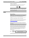
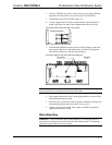
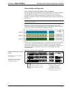
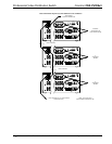
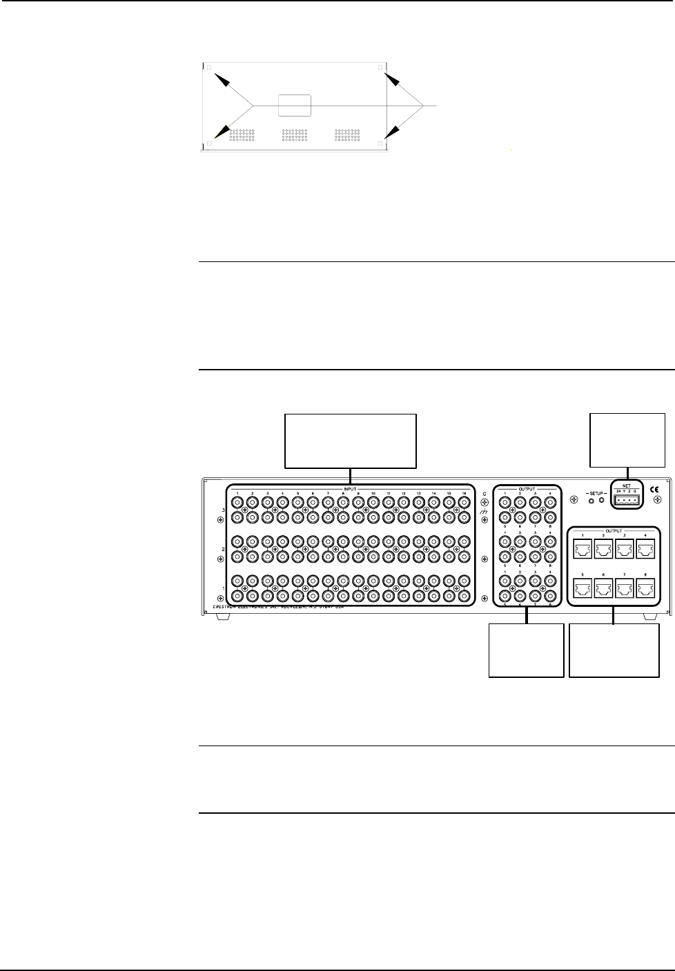
Hardware Hookup
Refer to the hookup diagram after this paragraph. Other than making the power
connection last, complete the connections in any order.
NOTE: For specific details regarding input connections, refer to "Hardware
Configurations" on page 15 if the CNX-PVID8x3 connects to Crestron Room
Solution Boxes within the system.
NOTE: Refer to "Network Wiring" on page 8 when making connections to the port
labeled NET.
Hookup Connections for the CNX-PVID8x3
FROM VIDEO SOURCES
(ACCEPTS COMPONENT,
S-VIDEO, NTSC/PAL COMPOSITE)
INPUT:
CRESNET:
TO CONTROL
SYSTEM AND
OTHER CRESNET
DEVICES
SINGLE ENDED
(LOCAL) VIDEO TO
MONITOR OR
DISPLAY
OUTPUT:
DIFFERENTIAL
VIDEO TO ROOM
SOLUTION BOX
OUTPUT:
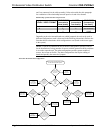
Hardware Configurations
NOTE: The hardware configurations described in the following sections only apply
to systems where the CNX-PVID8x3 connects to Crestron Room Solution Boxes.
The Crestron SystemBuilder can generate a program that fits into one of these
configurations.
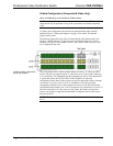
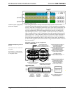
The CNX-PVID8x3 is constructed with three crosspoint boards; each implements a
16x8x1 matrix. The physical boards are labeled on the back of the unit as "levels" 1,
2, and 3 from bottom to top. Component sources connect to levels 1 through 3 per
input (connect Y to level 1, P
b
to level 2, and P
r
to level 3). S-video sources use
levels 1 and 2 per input (connect Y to level 1 and C to level 2). Composite sources
should connect to level 1 only (including level 3 extensions of level 1when boards 1