


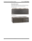
Crestron CNX-PVID8x3 Professional Video Distribution Switch
Operations Guide - DOC. 8159A Professional Video Distribution Switch: CNX-PVID8x3 • 7
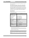
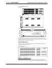
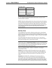
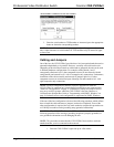
CNX-PVID8x3 Indicators
L
T
CRESTRON
L
NET
PWR
PR FEO SSI NOA
ES
TIVDE RTOISDBIU OINSWI
12345678 109 111213141516
13452678
CTE
2
1
3
HC
IAV TUEVPIECNOTDI
UTPUOT
CNX-PVID8X3
PWR (Power)
This LED illuminates when 24 volts DC from the network is supplied to the
CNX-PVID8x3.
NET
This LED illuminates when communication between the Cresnet system and the
CNX-PVID8x3 is established (unit is polled on the network). Illumination indicates
that the SIMPL Windows program currently loaded has a network device defined at
the same Net ID as the CNX-PVID8x3.
SELECT 1 - 3
These LEDs illuminate when a switcher board (levels 1 through 3) is selected.
Boards can be locally selected with the SELECT pushbutton. Refer to "SELECT
Pushbutton" on this page.
OUTPUT 1 - 8
These eight LEDs illuminate to indicate that a video source is routed via the
respective port to the corresponding room.
ACTIVE VIDEO INPUT
These 16 video sync indicators illuminate to signify active inputs on the selected
board (level).
NOTE: Only composite video and the "Y" S-video/component signal are reliably
detected. If connections to the INPUT connectors are made as recommended by
Crestron in "Hardware Configurations" on page 15, simply use level 1 for detection
of the sync signals.
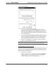
SETUP LED and Pushbutton
The rear panel SETUP pushbutton and its associated red LED are used for setup of
the unit’s network ID during the initial configuration of a Cresnet system or when
the device is being added/replaced. Refer to “Identity Code” on page 9 for detailed
information.
SELECT Pushbutton
The front panel SELECT pushbutton allows for local selection of the boards (levels 1
through 3). Three indicators are used as feedback.