


Setting Up Your Printer
Allegro2 17
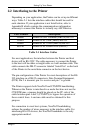
2.2 Interfacing to the Printer
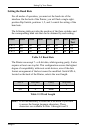
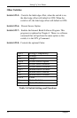
Depending on your application, the Printer can be set up in different
ways. Table 2-1 lists the interface cables that should be used for
each situation. If your application is not listed below, refer to
Appendix B which contains the communications information
necessary to connect the Printer to virtually any ASCII device.
Part Number Description
556000 Printer to CRT Terminal (DB25P) RS-232
556001 Printer to PC 9 Pin (DB9S) RS-232
556002 Printer to PC 25 Pin (DB25S) RS-232
899516 Printer to PC Parallel Port (DB25P)
Table 2-1 Interface Cables
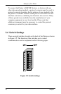
For most applications, the interface between the Printer and host
device will be RS-232C. The cable necessary to connect the Printer
to the host will be either a straight cable or a null-modem cable. This
cable connects the DB-25 connector labeled ‘Serial Port’ on the back
of the Printer to the serial data connector on the host device.
The pin configuration of the Printer for most descriptions of the RS-
232 interface on a DB-25 connector is Data Terminal Equipment,
(DTE). Pin 2 is transmit, pin 3 is receive and pin 7 is ground.
The Printer supports both Xon/Xoff and CTS/DTR handshaking.
Whenever the Printer is interfaced in a mode that does not use the
CTS/DTR pins, a jumper should be placed on the PC side of the
cable between pins 4 and 5 (CTS/RTS) to bypass the operation of
those control lines. A custom cable must be obtained for this
purpose.
For connection to most host systems, Xon/Xoff handshaking
reduces the number of wires necessary in the interface cable. For
interfacing RS-422 devices, the Xon/Xoff handshake is the only
appropriate method.