


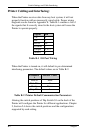
Switch Settings and Cable Interfacing
B-2 Allegro2
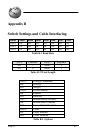
Printer Cabling and Interfacing:
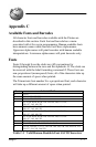
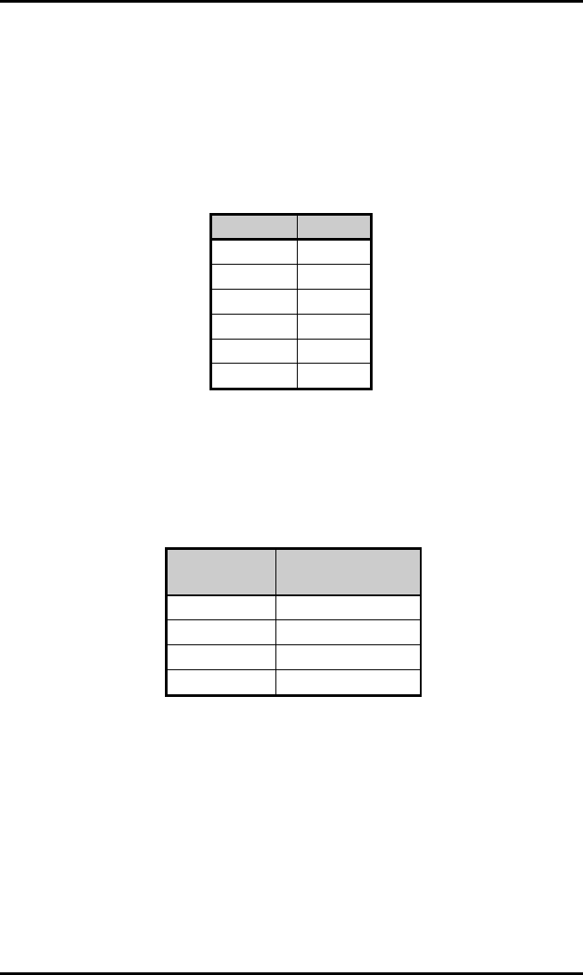
When the Printer receives data from any host system, it will not
properly function with an incorrectly wired cable. Proper wiring
diagrams can be found in Appendix E. Table B-1 contains a list of
the signals that if correctly wired to the host system will cause the
Printer to operate properly.
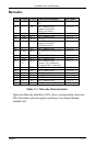
Signal Pin
TX 2
RX 3
BUSY 20
Ground 7
Jumper 4 to 5
Shield 1
Table B-1 I/O Port Wiring
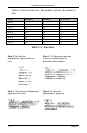
When the Printer is turned on, it will default to pre-determined
interfacing parameters. The default values are in Table B-2.
Paramete
r
Default Value
BAUD 9600
Data Bits 8
Parity None
Stop Bits 1
Table B-2 Printer Default Communication Parameters
Altering the switch positions of Dip Switch S1 on the back of the
Printer will configure the Printer for different applications. Chapter
2, Section 2.4 shows the switch positions and the configurations
supported by each setting.