


Setting Up Your Printer
18 Allegro2
2.3 Sample Installations
In this section, four typical installations are reviewed, CRT terminal,
PC, minicomputer, and mainframe computer. Cable connections for
similar installations are listed in Appendix D. This section outlines
the procedures that will enable you to set up the Printer for various
installations.
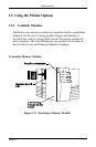
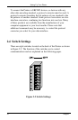
Connecting to a CRT
A typical application for a CRT-based system is generating and
printing labels that are stored on an optional Flash Module. First,
connect the Printer to the CRT with the cable number 556000 and
turn on switch 7 at the rear of the Printer. Next, plug the module
into the slot on the side of the Printer to store label formats on the
module. For a detailed explanation of the operation of this
configuration, refer to Section 3, “Creating Labels Using Internal
Batch Software.”
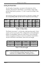
Connecting to a PC
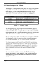
A cable should be selected (refer to Table 2-1), and connected to a
PC via a RS-232 port. It is recommended that you use a RS-232 port
to allow for two-way communication with the Printer. The RS-232
communications port can be connected with one of two possible
configurations: a 9 pin cable (part number 556001) or a 25 pin cable
(part number 556002).
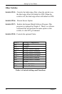
Note: DB25S (socket/female) connectors on most PCs are
normally parallel ports; DB25P and DB9P (pin/male)
are normally serial ports.