


dCS 974 User Manual Manual for Software Version 1.0x
dCS Ltd May 2001
Manual part no: DOC1241121A1
Page 18
Document No: OS-MA-A0124-112.1A1
Contact
dCS
on + 44 1799 531 999 email to: more@dcsltd.co.uk
(inside the UK replace + 44 with 0) web site: www.dcsltd.co.uk
Step 4 – Connecting the Outputs
Choose one of the following five sections:
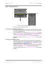
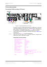
Connecting a Single AES or SPDIF Output
do this: If the Output Sample Rate is 88.2 or 96kS/s, check that your destination
equipment is capable of double speed operation.
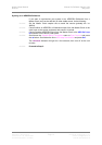
do this: If you have set Output Mode to Normal, connect the required single wire
output on the dCS 974 rear panel to the matching inputs on the destination
equipment using suitable cables. Signals are available from any of the four
AES/EBU outputs or the three SPDIF outputs simultaneously.
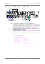
Connecting the SDIF-2 Output
do this: If the Output Sample Rate is 88.2 or 96kS/s, check that your destination
equipment is capable of double speed operation.
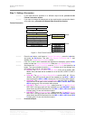
do this: If you have set Output Mode to Normal, connect the lower block of DSD/SDIF
connectors on the dCS 974 rear panel to the destination equipment using 3 coax
cables. Connect CH1 OUT to CH1 in, CH2 OUT to CH2 in and WCLK OUT to
CLK in.
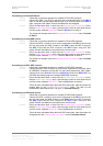
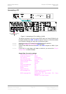
Connecting the Dual AES Outputs
do this: Check that your destination equipment is capable of Dual AES operation.
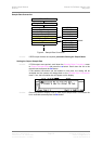
do this: If you have set Output Mode to Dual AES, connect the AES 1 output on the
dCS 974 rear panel to the AES 1 (or AES A) input on the destination equipment
and the AES 2 output to the AES 2 (or AES B) input, using two XLR cables.
Ensure the cables are not swapped. An identical Dual AES pair is available
from the AES 3 and AES 4 outputs.
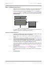
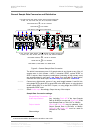
Connecting the Quad AES or DSD Quad Outputs
do this: Check that your destination equipment is capable of Quad AES or DSD Quad
operation.
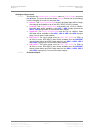
do this: If you have set Output Mode to Quad AES or DSD Quad, connect the AES 1
output on the dCS 974 rear panel to the AES 1 input on the destination
equipment, the AES 2 output to the AES 2 input, the AES 3 output to the AES 3
input and the AES 4 output to the AES 4 input, using four XLR cables. Ensure
the cables are not swapped.
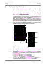
Connecting the DSD SDIF-2 or DSD SDIF-3 Output
do this: Check that your destination equipment is capable of DSD operation.
do this: If you have set Output Mode to DSD SDIF-2 or DSD SDIF-3, connect the lower
block of DSD/SDIF connectors on the dCS 974 rear panel to the destination
equipment using three coax cables. Connect CH1 OUT to CH1 in, CH2 OUT to
CH2 in and WCLK OUT to CLK in.
Note that the default setting for the DSD output clock is 44.1kS/s Wordclock
(rather than Bit clock at 2.82MS/s).
do this: Proceed to Step 5.