


dCS 974 User Manual Manual for Software Version 1.0x
dCS Ltd May 2001
Manual part no: DOC1241121A1
Page 73
Document No: OS-MA-A0124-112.1A1
Contact
dCS
on + 44 1799 531 999 email to: more@dcsltd.co.uk
(inside the UK replace + 44 with 0) web site: www.dcsltd.co.uk
PCM Input and/or Output Performance
Filtering
The normal filtering considerations of passband ripple, cutoff frequency and
rate, out of band (stop band) suppression, and transient/phase response apply
to sample rate converters.
The dCS 974 uses linear phase FIR filters to avoid the limit cycle problems that
come with many IIR filters. Linear phase gives filters a symmetrical transient
response before and after a transient (“pre-ringing” and “post ringing”). The
passband may or may not have a ripple
14
, depending on the conversion and/or
filter being used. Cutoff frequency is >40% of the lowest sampling rate used in
the conversion (input or output).
15
The stop band is typically below –110 dB,
but varies with conversion, and can be as low as –130 dB. The frequency
responses of two commonly used conversions (96kS/s ⇒ 44.1kS/s and 48kS/s
⇒ 44.1kS/s) are shown in Figure 41 and Figure 40 on page 99.
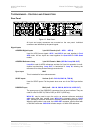
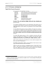
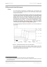
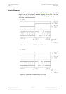
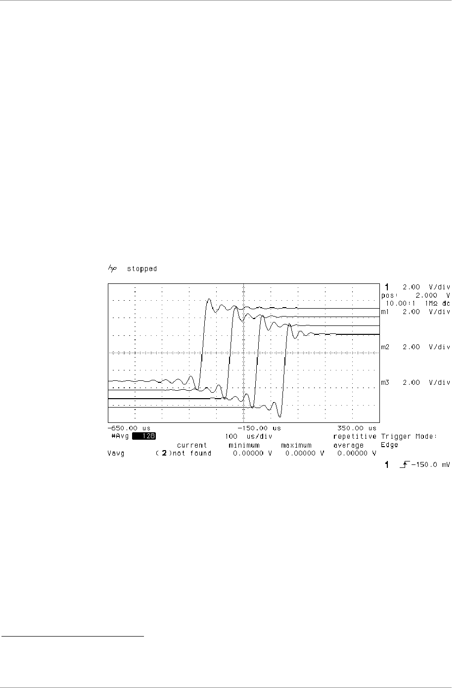
The transient responses of the filters in the 96 kS/s ⇒ 44.1 kS/s conversion are
shown below.
Figure 19 – Transient Performance of 44.1 kS/s Filter Options
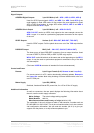
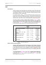
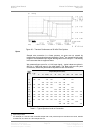
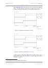
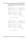
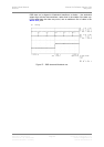
Use of higher sample rates gives much tighter transient response, with much
less energy smeared into the pre and post ringing. The transient responses of
the 96 kS/s output filters are shown below:
14
Filters always have some ripple. For “zero ripple” filters this is in the µdB to pdB region.
15
For conversions where the lowest rate used is 16 kS/s, 22.05 kS/s or 24 kS/s some conversions cut off at 33%
of the lowest sample rate.