


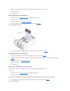
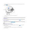
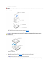

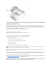
Figure 6-12. Securing Clip
6. Remove the heat sink.
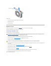
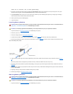
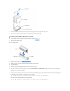
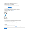
7. Pull the socket release lever straight up until the microprocessor is released (see Figure6-13).
8. Lift the microprocessor out of the socket and leave the release lever up so that the socket is ready for the new microprocessor.
Figure 6-13. Removing the Microprocessor
9. Unpack the new microprocessor.
If any of the pins on the microprocessor appear bent, see "Getting Help," for instructions on obtaining technical assistance from Dell.
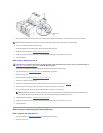
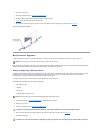
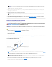
10. Align the pin-1 corner of the microprocessor (see Figure6-14) with the pin-1 corner of the microprocessor socket.
Identify the pin-1 corner of the microprocessor by locating the tiny gold triangle that extends from one corner of the large central rectangular area. The gold
maintain proper thermal conditions.
WARNING: The microprocessor chip and heat sink can become extremely hot. Be sure the microprocessor has had sufficient time to cool before
handling.
CAUTION: Be careful not to bend any of the pins when removing the microprocessor chip. Bending the pins can permanently damage the
microprocessor chip.
NOTE: Identifying the pin-1 corners is critical to positioning the microprocessor correctly.