


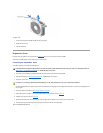
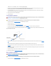

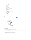
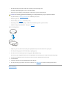
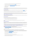
trianglepointstowardpin1,whichisalsouniquelyidentifiedbyasquarepad.
Figure 6-14. Pin-1 Identification
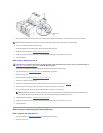
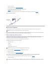
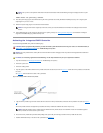
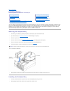
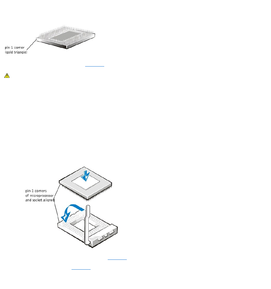
11. Install the microprocessor in the socket (see Figure6-15).
If the release lever on the microprocessor socket is not all the way up, move it to that position now.
With the pin-1 corners of the microprocessor and socket aligned, set the microprocessor lightly in the socket and make sure all pins are matched with the correct
holes in the socket. Because the system uses a ZIF micro-processor socket, there is no need to use force (which could bend the pins if the microprocessor is
misaligned). When the microprocessor is positioned correctly, it should drop down into the socket with minimal pressure.
When the microprocessor is fully seated in the socket, rotate the socket release lever back down until it snaps into place, securing the microprocessor.
Figure 6-15. Installing the Microprocessor
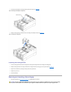
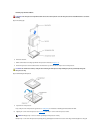
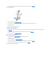
12. Place the new heat sink on top of the microprocessor (see Figure6-16).
13. Orient the securing clip as shown in Figure6-16.
Figure 6-16. Installing the Heat-Sink
CAUTION: Positioning the microprocessor incorrectly can permanently damage the microprocessor and the system when you turn on the
system. When placing the microprocessor in the socket, be sure that all of the pins on the microprocessor go into the corresponding holes. Be
careful not to bend the pins.