


Hardware Configuration Features B-9
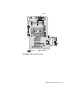
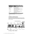
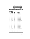
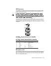
If you reconfigure your hardware, you may need pin number and signal information for
the parallel port connector. Figure B-4 illustrates the pin numbers for the parallel port
connector, and Table B-4 lists and defines the pin assignments and interface signals
for the parallel port connector.
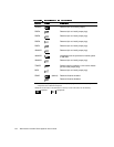
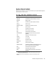
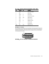
1 DCD I Data carrier detect
2 SIN I Serial input
3 SOUT O Serial output
4 DTR O Data terminal ready
5 GND N/A Signal ground
6 DSR I Data set ready
7 RTS O Request to send
8 CTS I Clear to send
9 RI I Ring indicator
Shell N/A N/A Chassis ground
25 14
13 1