


Installing System Components 61
6
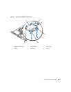
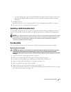
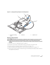
Connect the control panel interface cable to the FP_CONN1 connector on the system board. See
Figure 6-2 for the location of the connector.
7
Connect the optical drive interface cable to the IDE connector on the system board. See Figure 6-2 for
the location of the connector.
8
Close the system. See "Closing the System" on page 47.
Power Supply
The system supports a single nonredundant power supply.
Removing the Power Supply
CAUTION: Only trained service technicians are authorized to remove the system cover and access any of the
components inside the system. Before performing any procedure, see your Product Information Guide for
complete information about safety precautions, working inside the computer and protecting against electrostatic
discharge.
1
Open the system. See "Opening the System" on page 46.
2
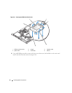
Disconnect the following power supply cables:
a
P3 from the hard drive cable harness
b
P2 from system board connector 12V
c
P1 from system board connector PWR_CONN
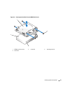
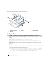
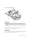
3
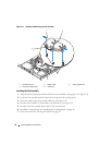
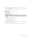
Using a #2 Phillips screwdriver, remove the screw at the front of the power supply that secures the
power supply to the chassis. See Figure 3-13.
4
Slide the power supply forward and lift straight up to remove the power supply from the chassis.