


Installing System Components 73
13
Set the processor lightly in the socket and ensure that the processor is level in the socket. When the
processor is positioned correctly, press it gently to seat it in the socket.
14
Close the processor cover.
15
Rotate the release lever back down until it snaps into place, securing the processor cover.
16
Install the heat sink.
a
Using a clean lint-free cloth, remove the existing thermal grease from the heat sink.
NOTE: Use the heat sink that you removed earlier in this procedure.
b
Apply thermal grease evenly to the top of the processor.
c
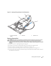
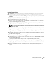
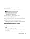
Place the heat sink onto the processor. See Figure 3-18.
d
Using a #2 Phillips screwdriver, tighten in a diagonal pattern the four captive screws that secure
the heat sink to the system board. See Figure 3-18.
17
Install the cooling shroud. See "Installing the Cooling Shroud" on page 48.
18
Close the system. See "Closing the System" on page 47.
As the system boots, it detects the presence of the new processor and automatically changes the system
configuration information in the System Setup program.
19
Press <F2> to enter the System Setup program, and check that the processor information
matches the
new system configuration.
See "Using the System Setup Program" on page 29.
20
Run the system diagnostics to verify that the new processor operates correctly.
See "Running the System Diagnostics" on page 93 for information about running the diagnostics and
troubleshooting processor problems.
Control Panel Assembly (Service-Only Procedure)
Removing the Control Panel Assembly
CAUTION: Only trained service technicians are authorized to remove the system cover and access any of the
components inside the system. Before performing any procedure, see your Product Information Guide for
complete information about safety precautions, working inside the computer and protecting against electrostatic
discharge.
1
Open the system. See "Opening the System" on page 46.
2
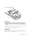
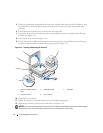
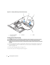
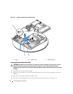
Disconnect the control panel cables. See Figure 3-20.
3
Using a #2 Phillips screwdriver, remove the two screws that secure the control panel assembly to the
chassis. See Figure 3-20.
4
Carefully lift the back of the control panel assembly to clear the chassis mounting studs, and remove
the assembly from the system.