


Installing System Components 153
2
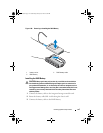
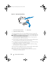
Remove the processor from the packing material by the processor’s edges
only. Do not touch the bottom of the processor. Handle the processor
carefully with your fingers on the side edges. Place your hand beneath the
processor when you are moving it to the system.
3
Locate the pin 1 indicator on the system board socket.
4
Locate the pin 1 indicator on the top of the processor. The pin 1 indicator
is shown as a triangle on the top of the processor. See
Figure 3-30
.
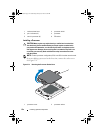
CAUTION: Positioning the processor incorrectly can permanently damage the
system board or the processor. Be careful not to bend the pins in the socket.
5
Place the processor over the socket with each pin 1 aligned and level. See
Figure 3-30.
6 Align the notches in the
p
rocessor with the
socket keys on t
he ZIF
socket. See
Figure 3-30.
7
I
nstall the processor in the socket. Keep the processor level (see
Figure 3-30
) and insert it straight down into the socket.
Allow the
processor to float on the pins, allowing the processor shield to hold it in
place.
8
Verify that the processor is properly aligned and seated.
9
Close the processor shield. See Figure 3-30.
10
R
otate the socket-release lever down until it snaps into place. See
Figure 3-30
.
11
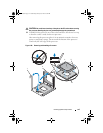
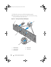
Using a clean lint-free cloth, remove the thermal grease from the heat sink.
CAUTION: Applying too much thermal grease can result in excess grease coming
in contact with and contaminating the processor socket.
12
Open the grease applicator included with your processor kit and apply all
of the thermal grease in the applicator to the center of the topside of the
new processor.
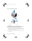
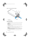
13 Place the heat sink on the processor. See
Figure 3-29
.
14 Close the heat-sink release levers
. See Figure 3-29.
15
Install the cooling fan assembly. See "Installing the Cooling Fan Assembly"
on page 120.
16
Install the memory risers. See "Installing a Memory Riser" on page 101.
book.book Page 153 Wednesday, January 20, 2010 10:20 AM