


Removing and Installing Parts: Dell Dimension E520 Service Manual
file:///T|/htdocs/systems/dimE520/en/SM_EN/parts.htm[10/16/2012 1:05:24 PM]
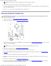
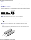
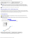
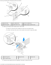
1 Channel A: matched pair of memory
modules in connectors DIMM_1 and DIMM_2
(white securing clips)
2 Channel B: matched pair of memory
modules in connectors DIMM_3 and
DIMM_4 (black securing clips)
NOTICE: If you remove your original memory modules from the computer during a memory upgrade, keep them
separate from any new modules that you may have, even if you purchased the new modules from Dell. If possible, do
not pair an original memory module with a new memory module. Otherwise, your computer may not start properly.
You should install your original memory modules in pairs either in DIMM connectors 1 and 2 or DIMM connectors 3 and
4.
NOTE: Memory purchased from Dell is covered under your computer warranty.
Addressing Memory With 4-GB Configurations
Your computer supports a maximum of 4 GB of memory when you use four 1-GB DIMMs. Current 32-bit operating systems,
such as Microsoft
®
Windows
®
XP, can use a maximum of 4 GB of address space; however, the amount of memory available
to the operating system is less than that installed. Certain components within the computer require address space in the 4-GB
range. Any address space reserved for these components cannot be used by computer memory.
Installing Memory
CAUTION: Before you begin any of the procedures in this section, follow the safety instructions in the
Product Information Guide.
NOTICE: To prevent static damage to components inside your computer, discharge static electricity from your body
before you touch any of your computer's electronic components. You can do so by touching an unpainted metal surface
on the computer chassis.
1. Follow the procedures in Before You Begin
.
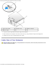
2. Remove the computer cover (see Removing the Computer Cover
).
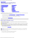
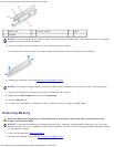
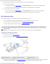
3. Press out the securing clip at each end of the memory module connector.
1 memory connector closest to processor 2 securing clips (2) 3 connector
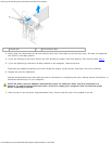
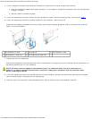
4. Align the notch on the bottom of the module with the crossbar in the connector.