


Removing and Installing Parts: Dell Dimension E520 Service Manual
file:///T|/htdocs/systems/dimE520/en/SM_EN/parts.htm[10/16/2012 1:05:24 PM]
7. Pivot the socket release lever back toward the socket and snap it into place beneath the securing tab.
NOTICE: If you are not installing a processor upgrade kit from Dell, reuse the original heat sink assembly when you
replace the processor.
If you installed a processor replacement kit from Dell, return the original heat sink assembly and processor to Dell in
the same package in which your replacement kit was sent.
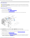
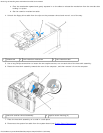
8. Install the heat sink assembly:
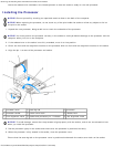
a. Place the heat sink assembly back onto the heat sink assembly bracket.
b. Rotate the heat sink assembly down towards the computer base and tighten the two captive screws.
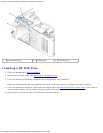
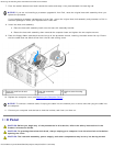
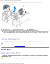
9. Place the floppy ribbon cable back across the top of the processor shroud, inserting the cable under the clip. Ensure
that the cable does not block airflow from the fan and cooling vents.
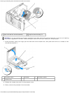
1 heat sink and fan shroud
assembly
2 heat sink assembly
bracket
3 captive screw housing
(2)
10. Replace the computer cover (see Replacing the Computer Cover
).
NOTICE: To connect a network cable, first plug the cable into the network port or device and then plug the cable into
the computer.
11. Connect your computer and devices to electrical outlets, and then turn them on.
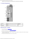
I/O Panel
CAUTION: Before you begin any of the procedures in this section, follow the safety instructions in the
Product Information Guide.
CAUTION: To guard against electrical shock, always unplug your computer from the electrical outlet before
opening the cover.
CAUTION: The heat sink assembly, power supply, and other components may be very hot during normal