


Replacing the Camera and Microphone Assembly
Before working inside your computer, read the safety information that shipped with your computer. For additional safety best practices information, see the
Regulatory Compliance Homepage at: www.dell.com/regulatory_compliance.
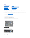
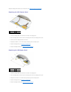
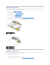
1. Slide the cable connector of the camera/microphone cable into the connector on the camera/microphone assembly.
2. Close the lever on the connector on the camera/microphone assembly.
3. Angle in and align the camera/microphone assembly with the notch on the display cover.
4. Tighten the M2 x 3-mm screw securing the camera/microphone assembly to the display cover.
5. Replace the display bezel (see Replacing the Display Bezel).
6. Replace the display assembly (see Replacing the Display Assembly).
Removing the Latch Hook Assembly
Before working inside your computer, read the safety information that shipped with your computer. For additional safety best practices information, see the
Regulatory Compliance Homepage at: www.dell.com/regulatory_compliance.
1. Follow the instructions in Before Working on Your Computer.
2. Remove the display assembly (see Removing the Display Assembly).
3. Remove the display bezel (see Removing the Display Bezel).
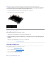
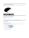
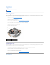
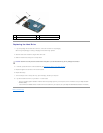
4. Remove the M2.5 x 5-mm screw.
5. Push in from the front and lift the stabilizer bars to pull out.
Replacing the Latch Hook Assembly
Before working inside your computer, read the safety information that shipped with your computer. For additional safety best practices information, see the
Regulatory Compliance Homepage at: www.dell.com/regulatory_compliance.
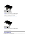
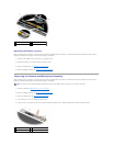
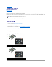
1. Place the latch hook assembly on the display cover, aligning the screw holes on the assembly and the cover.
2. Replace the M2.5 x 5-mm screw.
3. Replace the display bezel (see Replacing the Display Bezel).
4. Replace the display assembly (see Replacing the Display Assembly).
1
M2.5 x 5-mm screw
2
latch hook assembly
3
display cover