


Back to Contents Page
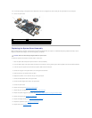
System Board Assembly
Dell™Latitude™E6500ServiceManual
Removing the System Board Assembly
Replacing the System Board Assembly
The system board's BIOS chip contains the Service Tag, which is also visible on a barcode label on the bottom of the computer. The replacement kit for the
system board includes media that provides a utility for transferring the Service Tag to the replacement system board.
Removing the System Board Assembly
Before working inside your computer, read the safety information that shipped with your computer. For additional safety best practices information, see the
Regulatory Compliance Homepage at: www.dell.com/regulatory_compliance.
1. Follow the instructions in Before Working on Your Computer.
2. Close the display and turn the computer over.
3. Remove the bottom of the base assembly (see Removing the Bottom of the Base Assembly).
4. Remove the Mini-Card from the WWAN/FCM card slot, if present (see Removing a WWAN Card or Removing an FCM).
5. Remove the Mini-Card from the WLAN/WiMax card slot, if present (see Removing a WLAN/WiMax Card).
6. Remove the hinge covers (see Removing the Hinge Covers).
7. Remove the Mini-Card in the WPAN/UWB/FCM card slot, if present (see Removing a WPAN/UWB Card or Removing an FCM).
8. Remove the hard drive (see Removing the Hard Drive).
9. Disconnect the coin-cell battery cable from the system board (see Removing the Coin-Cell Battery).
10. Remove the memory modules (see Removing a Memory Module).
11. Remove the processor thermal-cooling assembly (see Removing the Processor Thermal-Cooling Assembly).
12. Remove the processor (see Removing the Processor Module).
13. Remove the fan (see Removing the Fan).
14. Remove the optical drive (see Removing the Optical Drive).
15. Remove the display assembly (see Display).
16. Remove the keyboard (see Removing the Keyboard).
17. Remove the speaker/fingerprint reader cover (see Removing the Right- Speaker and Fingerprint Reader Cover).
18. Remove the palm rest assembly (see Removing the Palm Rest Assembly).
19. Remove the card cage (see Removing the Card Cage).
20. Disconnect the power cable.
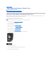
21. Disconnect the Secure Digital card cable from the system board.
22. Disconnect the ExpressCard cable from the system board.
23. Disconnect the I/O daughter card cable from the system board.
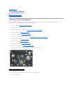
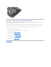
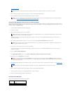
24. Remove the five M2.5 x 5-mm screws labeled with white arrows from the system board.
25. Pull out on the top left corner of the base assembly to release the power, USB, and serial connectors.