


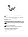

1. Ensure that you read the Safety instructions.
2. Keep the #1 Phillips screwdriver ready.
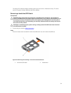
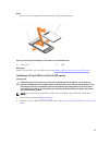
3. Remove the hard drive/SSD cage.
NOTE: You must remove the hard drive/SSD cage to replace a faulty hard drive/SSD cage or
service other components inside the system.
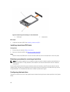
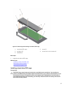
Steps
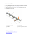
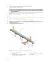
1. Align the screw holes on the hard drive/SSD cage with the screw holes on the chassis.
2. Lower the hard drive/SSD cage into the chassis until it is seated firmly in place.
3. Install the five screws to secure the hard drive/SSD cage to the chassis.
Next steps
1. Install the hard drive/SSD backplane.
2. Install the hard drive(s)/SSD(s).
3. Follow the procedure listed in After working inside your system.
Related Links
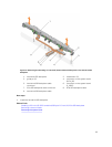
Removing a hard drive/SSD cage
Installing the system cover
Installing a server module
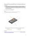
Hard drive/SSD backplane
Backplane Configuration
2.5 inch (x4) SAS
backplane
A full-length SAS hard drive/SSD backplane with a
backplane cable. It supports up to four 2.5 inch SAS
hard drives/SSDs.
2.5 inch (x4) SATA
backplane
A full-length SAS hard drive/SSD backplane with a
backplane cable. It supports up to four 2.5 inch
SATA hard drives/SSDs.
2.5 inch (x2) SATA
plus 2.5 inch (x2)
PCIe backplane
A full-length backplane with two backplane cables.
It supports up to two 2.5 inch SATA hard drives/
SSDs and two 2.5 inch PCIe SSDs. For information
about populating drives in the bay, see Hard
drive/SSD bay numbering.
1.8 inch (x12) SAS
SSD backplane
A full-length SAS SSD backplane with two backplane
cables. It supports up to twelve 1.8 inch SAS SSDs.
NOTE: All drives connect to the system board through the hard-drive/SSD backplane cable
connector.
The following table provides information about connecting different backplane configurations to the
respective connectors on the system board and expander card.
88