


7. Remove the display assembly (see Removing the Display Assembly).
8. Remove the keyboard (see Removing the Keyboard).
9. Remove the card in the WWAN/FCM slot, if present (see Removing a WWAN Card).
10. Remove the card in the WLAN/WiMax slot, if present (see Removing a WLAN Card).
11. Remove the card in the WPAN/UWB/FCM slot, if present (see Removing a WPAN/UWB Card).
12. Remove the memory modules (see Removing a Memory Module).
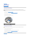
13. Remove the fan (see Removing the Fan).
14. Remove the processor heat sink (see Removing the Processor Heat Sink).
15. Remove the discrete graphics heat sink (see Removing the Discrete Graphics Heat Sink).
16. Remove the coin-cell battery (see Removing the Coin-Cell Battery).
17. Disconnect the DC power cable from the system board. The DC power connector is the seven-wire connector located near the processor.
18. Remove the palm rest assembly (see Removing the Palm Rest Assembly).
19. Remove the SD card reader assembly (see Removing the SD Card Reader).
20. Remove the Express card cage assembly (see Removing the Express Card Cage).
21. Disconnect the orange I/O board cable from the system board.
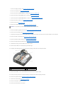
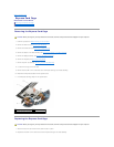
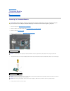
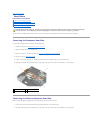
22. Remove the two M2 x 3-mm screws securing the PC card cage.
23. Uncouple the PC card cage from its mounting bracket by lifting the latch tab with a small plastic scribe.
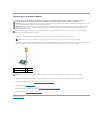
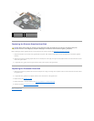
24. Remove the five M2.5 x 5-mm screws labeled with white arrows from the system board.
25. Pull out on the top, left corner of the base assembly to release the DC, USB, and display connectors.
26. Remove the system board (see Removing the System Board Assembly).
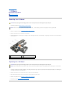
27. Remove the I/O board (see Removing the I/O Board).
28. Remove the DC power cable from the base.
29. Remove the modem cable from the base.
NOTICE: In this procedure, do not detach the processor from the system board.
1
M2 x 3-mm screw (2)
2
PC card cage
3
latch tab
4
plastic scribe