


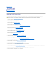
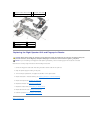
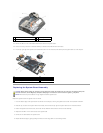
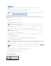

25. Remove five M2.5 x 5-mm screws labeled with white arrows from the system board.
26. Pull out on the top, left corner of the base assembly to release the DC, USB, and serial connectors.
27. Lift the top, right edge of the system board to disconnect the it from the I/O board, then carefully lift the system board out of the computer.
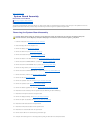
Replacing the System Board Assembly
Replace the system board in the opposite order of removal.
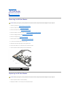
1. Insert the bottom edge of the system board into the base of the computer, ensuring the system board is under the metal latch mechanism.
2. Place the top, left corner of the system board into the base, then connect the top right of the system board to the I/O board connector.
3. Position the system board into the base, ensure that the DC, USB, and serial connectors fit into the base assembly.
4. Replace the five M2.5 x 4-mm screws to secure the system board.
5. Connect the I/O board cable to the system board.
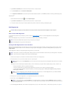
6. Replace the PC card cage by gently pushing the inward end of the cage down over its mounting bracket.
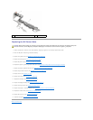
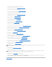
1
M2 x 3-mm screw (2)
2
PC card cage
3
latch tab
4
plastic scribe
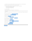
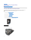
1
SD cable and Express card cage cable connectors
2
DC power cable connector
3
I/O board cable connector
4
system board
5
M2.5 x 5-mm system board screws (5)
CAUTION: Before working inside your computer, read the safety information that shipped with your computer. For additional safety best
practices information, see the Regulatory Compliance Homepage on www.dell.com at: www.dell.com/regulatory_compliance.
NOTICE: Ensure that any loose cables do not get caught beneath the system board.