102 Installing System Components
5
Install the memory modules in the same sockets from which they were
removed. See "Installing a Memory Module" on page 77.
6
Install the expansion cards and connect any cables. See "Installing an
Expansion Card" on page 72.
7
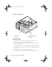
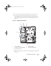
Depending on your configuration, connect the following cables that you
removed in "Removing the System Board" on page 100. See Figure 6-2.
• Two power-supply cables to the POWER and POWER12V1
connectors
• If applicable, diskette data cable to the FLOPPY connector
• I/O panel cable to the CONTROL-PANEL connector
• Processor cooling fan cable to the FAN1 connector
• Card cage cooling fan cable to the FAN2 connector
• SATA hard-drive data cable(s) to the SATA connector(s)
• Intrusion switch cable from the INTRUSION connector
8
Close the system. See "Closing the System" on page 47.
9
Reconnect the system to the electrical outlet, and turn on the system.
book.book Page 102 Wednesday, April 15, 2009 8:47 PM


