10/100 Fast Ethernet Switch User’s Guide
Identifying External Components
11
♦
Port 2x (Port number two) is a shared connection with the (Media
Independent Interface) MII port in the back of the Switch. Note that,
whenever there is a connection at the MII port, port 2x is unavailable
for connection to other devices.
♦
Uplink/ MDI-II (media dependent interface) port for uplink to
another switch, hub or repeater.
♦
RS-232 DCE console port for diagnosing the Switch via a connection
to a PC and Local Console Management.
♦
Comprehensive LED indicators that display the conditions of the
Switch and status of the network. A description of these LED
indicators follow (see
LED Indicators
).
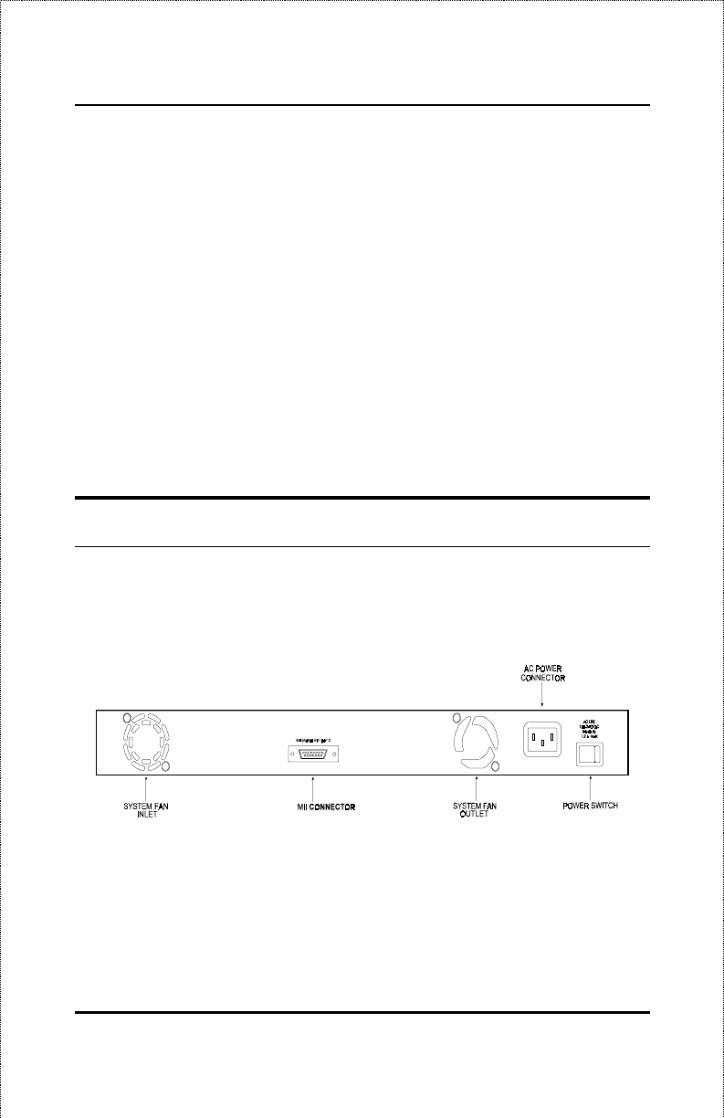
Rear Panel
The rear panel of the Switch consists of a power switch, an AC power
connector, system fans and MII port. The following shows the rear panel of
the Switch.
Figure 3-2. Rear panel view of the DES-3208
♦
Power Switch.
This turns the Switch on and off. To turn on the
system, press the switch to the “ 1” position; to turn off, press the
switch to the “ 0” position.


