


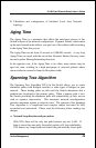

10/100 Fast Ethernet Switch User’s Guide
Switch Management
29
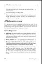
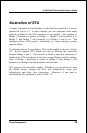
Illustration of STA
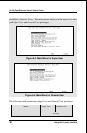
A simple illustration of three Bridges (or the Switch) connected in a loop is
depicted in
Figure
5-1
. In this example, you can anticipate some major
network problems if the STA assistance is not applied. For instance, if
Bridge 1 broadcasts a packet to Bridge 2, Bridge 2 will broadcast it to
Bridge 3, and Bridge 3 will broadcast it to Bridge 1...and so on. The
broadcast packet will be passed indefinitely in a loop, causing a serious
network failure.
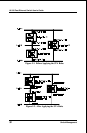
To alleviate network loop problems, STA can be applied as shown in
Figure
5-2. In this example, STA breaks the loop by blocking the connection
between Bridge 1 and 2. The decision to block a particular connection is
based on the STA calculation of the most current Bridge and Port settings.
Now, if Bridge 1 broadcasts a packet to Bridge 3, then Bridge 3 will
broadcast it to Bridge 2 and the broadcast will end there.
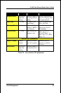
STA setup can be somewhat complex. Therefore, you are advised to keep
the default factory settings and STA will automatically assign root
bridges/ports and block loop connections. However, if you need to
customize the STA parameters, refer to
Table 5-1
.