


3 Product Introduction D-Link Web Smart Switch User Manual
Front Panel
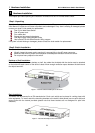
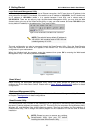
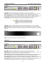
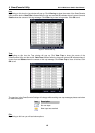
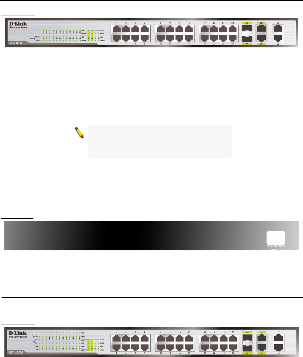
Figure 8 – DES-1228 Front Panel
Power LED: The Power LED lights up when the Switch is connected to a power source.
CPU LED: When the CPU LED is blinking, then the switch is in the normal condition. If the CPU LED is off or
stays in solid light state that means the system might have crashed or firmware upgrade has failed.
Port Link/Act LED (1-28): The Link/Act LED flashes which indicates a network link through the
corresponding port. Blinking indicates that the Switch is either sending or receiving data to the port..
FX Link LED (25-26): The FX Link sign lights up indicate that MiniGBIC ports is used.
NOTE: On DES-1228, the MiniGBIC ports are
shared with normal RJ-45 ports 25 and 26. When
MiniGBIC port is used, the RJ-45 port cannot be
used.
100M LED (1-28): The 100M LED sign lights up when the corresponding port is running on 100Mbps.
1000M LED (27-28): The 1000M LED sign lights up when the corresponding port is running on 1000Mbps.
Reset: By pressing the Reset button the Switch will change back to the default configuration and all changes
will be lost.
Rear Panel
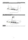
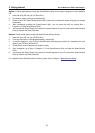
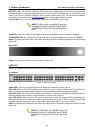
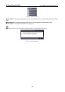
Figure 9 – DES-1228 Rear Panel
Power: The power port is where to connect the AC power cord.
DES-1228P
24-Port 10/100Mpbs PoE Smart Switch with 4-Port 10/100/1000Mbps and 2 Combo SFPs
Front Panel
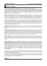
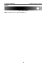
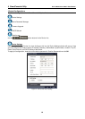
Figure 10 – DES-1228P Front Panel
Power LED: The Power LED lights up when the Switch is connected to a power source.
Power Max LED: The Power Max lights up when the system power resource remain ≦15.4W, in the
meantime, system will not provide power to the additional PoE PD inserted.
CPU LED: When the CPU LED is blinking, then the switch is in the normal condition. If the CPU LED is off or
stays in solid light state that means the system might have crashed or firmware upgrade has failed.
Port Link/Act LED (1-28): The Link/Act LED flashes which indicates a network link through the
corresponding port. Blinking indicates that the Switch is either sending or receiving data to the port.
Fan OK/Fail LED: The FAN LED shows the status of the fans, the green light (OK) indicates that all fans
work fine and the red light (Fail) indicate that on or multiple fans are working abnormally.
8
8