


Using the Monitor Panel
5-5
EATON Powerware
®
9315 UPS (200–300 kVA) Operatio n Manual S 164201036 Rev F powerware.com
Ī
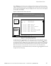
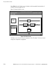
Graphics - Displays a real-time graphic representation of the flow of current through
the internal UPS components.
Ī Setup - Allows you to configure the UPS communication port and set the date and time
for the timestamp.
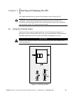
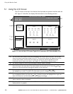
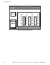
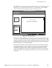
Figure 5-3 shows the LCD screen as it appears when you first start the UPS. The Meters
menu is displayed in the menu box, with the System option highlighted. In the information
area, the system meters show their current readings.
Uninterruptible Power System
System Normal
Alarm: None
Notice: None
Meters
System
Load Amps
Events Statistics Graphics Setup
Input Output
Bypass Battery
VAB
480
VBC VCA
KW
379
KVA
399
IA IB IC
FREQ
60.0
PF
0.95
V
540
I
000
Meters
480
480 480
480480
VAB
480
VBC VCA
480 480
IA IB IC
361 361361
IN
000
VAB
480
VBC VCA
480 480
FREQ
60.0
KVA
300
KW
240
PF
0.80
Battery
04 MAY 1997 14:23:45
100%
Percent
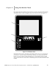
Figure 5 -3. System Meters Screen (Typical for Powerware 9315 300 480/480V UPS)
The Input area shows the phase-to-phase voltage, frequency, and phase current of the
incoming utility, followed by the kVA, KW, and power factor measurements. The output
area shows the same information for the power being output by the UPS.
TheBypassareashowsthephase-to-phasevoltageofthebypasssource.TheBatteryarea
displays the DC voltage (V) and the DC current (I).
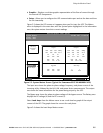
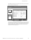
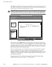
Select Load Amps from the Meters menu to see a real-time bar graph of the output
current of the UPS. The graph shows the current for each phase.
Figure 5-4 shows the Load Amps Meters screen.