


6-1
EATON Powerware
®
9315 UPS (200–300 kVA) Operatio n Manual S 164201036 Rev F powerware.com
Chapter 6 Using Features and Options
You can add available options and accessories to enhance the performance of your UPS
system. This chapter provides detailed descriptions of some of the features and options
introduced earlier in this manual.
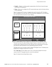
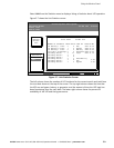
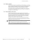
6.1 Building Alarm Monitoring
This standard feature lets you connect the UPS to your building alarms, such as smoke
detectors or overtemperature alarms. The terminals for external connections are located
inside the UPS on the customer interface panel (see Figure 6-1).
TB1
BLDG ALARM1
BLDGALARM 4
BLDGALARM 5
NOTE:
All b uilding alarm inputs or remote
features require an isolated, normally
open contact or s witch (rated at
24 Vdc 20 mA minimum) connected
between the alarm in put terminal and
common terminal as shown. All
control wiring, relay, and switch
contacts are customer-provided.
1
2
3
4
5
6
7
8
9
15
10
11
14
13
12
TB2
BLDGALARM 2
BLDGALARM 3
BLDGALARM 6
1
2
3
4
5
6
7
8
9
15
10
11
14
13
12
ONBYPASS
BATTERYCONTACTORCLOSED
RELAY2 NO
ONINV
RELAY2 NC
RELAY1 NO
RELAY1 NC
BLDGALARM 1RTN
BLDGALARM 4RTN
BLDGALARM 5RTN
BLDGALARM 2RTN
BLDGALARM 3RTN
BLDGALARM 6RTN
REMOTE EPO
REMOTEEPORTN
ONBYPASSRTN
BATTERY CONT RTN
ONINV RTN
ALARMRTN
NOTICE RTN
RS-232
RS-485
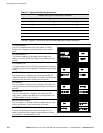
Figure 6-1. External Connections for Building Alarm Monitoring
Regardless of how you assign the building alarms, they display as Building Alarm 1, Building
Alarm 2, Building Alarm 3, etc., on the LCD screen of the Monitor Panel. You should use
twisted-pair wires for each alarm input and common.