Using Features and Options
6-7
EATON Powerware
®
9315 UPS (200–300 kVA) Operatio n Manual S 164201036 Rev F powerware.com
6.7 Supervisory Contact Module
An optional SCM establishes an interface between the UPS manufacturer’s equipment and
thecustomer’smonitor.Thisinterfaceallowsthe customer to monitor operational status
of the UPS equipment. A maximum of two m onitoring accessories (RMPs, RIMs, or SCMs)
can be installed. See Table 6 -1 on page 6-4 for the number of accessories permitted.
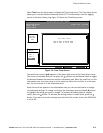
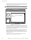
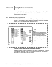
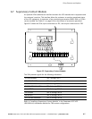
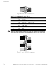
Figure 6-5 shows the SCM, input connections on TB1, and output connections on TB2.
TB2
Figure 6-5. Supervisory Contact Module
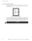
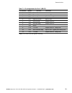
The SCM provides signals for the following indications:
SYSTEM NORMAL
TB2-1 through TB2-3
NO REDUNDANCY
TB2-4 through TB2-6
ON GENERATOR
TB2-7 through TB2-9
BYPASS NOT AVAILABLE
TB2-10 through TB2-12
ON BATTERY
TB2-13 through TB2-15
UPS ALARM
TB2-16 through TB2-18
ON BYPASS
TB2-19 through TB2-21
SHUTDOWN IMMINENT
TB2-22 through TB2-24
Refer to “Installing a Supervisory Contact Module” in the Powerware 9315 UPS
(200–300 kVA) Installation Manual for TB2 contact configurations.


