


8
• TP Port and Cable Installation
⇒ In the switch, TP port supports MDI/MDI-X auto-crossover, so both types of
cable, straight-through (Cable pin-outs for RJ-45 jack 1, 2, 3, 6 to 1, 2, 3, 6 in
10/100M TP; 1, 2, 3, 4, 5, 6, 7, 8 to 1, 2, 3, 4, 5, 6, 7, 8 in Gigabit TP) and
crossed-over (Cable pin-outs for RJ-45 jack 1, 2, 3, 6 to 3, 6, 1, 2) can be used.
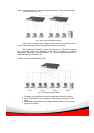
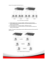
⇒ Use Cat. 5 grade RJ-45 TP cable to connect to a TP port of the switch. Connect
the other end to a network-aware device, such as a workstation or a server.
⇒ Repeat the above steps as needed, for each RJ-45 port to be connected to a
Gigabit 10/100/1000 TP device.
The switch is now in operation.
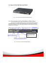
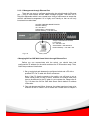
• Power On
The switch supports 100-240 VAC, 50-60 Hz power sources.The power
supply will automatically convert the local AC power source to DC power. After the
power is on, all LED indicators will flash once except the power LED which will stay
on. This represents a reset of the system.
• Firmware Loading
Once reset, the bootloader will load the firmware into the memory. It will take
about 30 seconds.
Once firmware loading is finished the switch will flash all LEDs
once and automatically perform a self test and then in ready state.
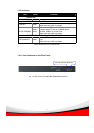
2-1-2. Cabling Requirements
To help ensure a successful installation and optimize the network
performance, please carefully follow the cabling requirements. Using cables under
the requirement.