


Electro Industries/GaugeTech
Doc # E107706 V1.25 9-5
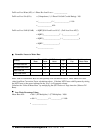
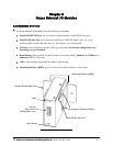
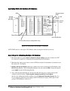
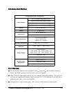
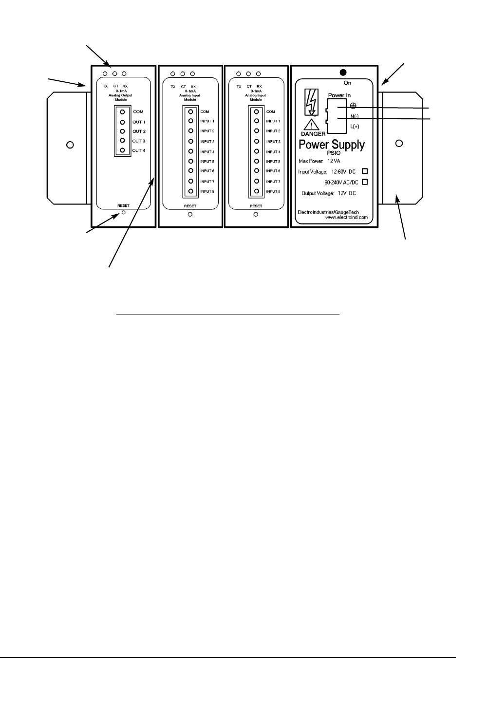
Mounting Bracket
Communication
ONLY
(A+, B- and
Shield)
Female
RS-485
Side Port
LEDs
Control
Power
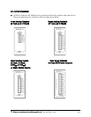
I/O Port (Size and pin configuration vary)
Reset Button
9.3:
Using
PSIO
with
Multiple
I/O
Modules
9.3.1:
Steps
for
Attaching
Multiple
I/O
Modules
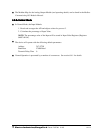
1. Each I/O module in a group must be assigned a unique address. See the Communicator EXT
User Manual for details on configuring and programming the I/O Modules.
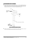
2. Determine how many power sources (such as PSIO) are needed for the number of modules in use.
See section 9.2.1 for details.
3. Starting with the left module and using a slotted screw driver, fasten the first I/O Module to the
left Mounting Bracket. The left Mounting Bracket is the one with the PEM. Fasten the internal
screw tightly into the left Mounting Bracket.
4. Next, slide the female RS-485 port into the male RS-485 side port to connect the next I/O
module to the left module. Fasten together enough to grab but do not tighten.
One by one combine the modules together using the Integrated Fastening System (Fig. 9.1).
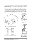
If you require an additional power supply, attach a PSIO (power supply) to the right of each
group of 4 I/O Modules (section 9.3).
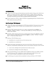
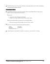
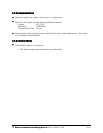
Figure 9.6: Using PSIO with Multiple I/O Modules
NOTE: PSIO must be to the right of I/O Modules when viewing the side label (as shown).